00198382-03_UM_SIPLACE-CA4-V2_EN.pdf - 第196页
5 Tasks at the placement machine Instruction manual SIPLACE CA4 V2 5.1 Staff profiles From software version 713.0 Edition 12/2019 196 5.1.3 Operator level " Service (customer)" 5.1.3.1 T asks The servic e perso…
Instruction manual SIPLACE CA4 V2 5 Tasks at the placement machine
From software version 713.0 Edition 12/2019 5.1 Staff profiles
195
– Splicing materials:
– Splicing plates (4000), item no. 00318671-xx
– SMD tape connector 4.3 mm (4000), item no. 00356343-xx)
– SMD tape connector 16 mm (1000), item no. 00356344-xx)
– Erasers or fiberglass pens to remove fiducials
– Indelible pens for marking the tracks
– Vacuum cleaner with suitable nozzle
5.1.2 Operator level "Advanced production"
5.1.2.1 Tasks
The line engineers should be assigned the following tasks:
– Acting as a contact for the operators
– Managing the logbook
– Monitoring and carrying out preventive maintenance at the specified intervals
– Monitoring the workplace to ensure that it is clean and safe
– Monitoring conformity with ESD regulations
– Carrying out quality control
– Following up and reporting fault messages
– Making sure that errors have been eliminated
– Providing all materials required to produce the job in a timely manner, such as
–PCBs
– Splicing materials
– Soldering paste
– Components
– Feeder modules, etc.
– Setting up the station for a new production batch
– Checking the feeder module settings:
– Increment
– Pickup position
– Checking the management data
– Checking the management data from OIS or SIPLACE Explorer
– Asking the responsible programmers to modify placement programs
– Ensuring a smooth flow of information between the individual groups
5 Tasks at the placement machine Instruction manual SIPLACE CA4 V2
5.1 Staff profiles From software version 713.0 Edition 12/2019
196
5.1.3 Operator level "Service (customer)"
5.1.3.1 Tasks
The service personnel's duties include:
– Major preventive maintenance jobs
– Mounting replacement parts
– Editing machine data
– Calibrating the placement machine
Instruction manual SIPLACE CA4 V2 5 Tasks at the placement machine
From software version 713.0 Edition 12/2019 5.2 Controls and displays
197
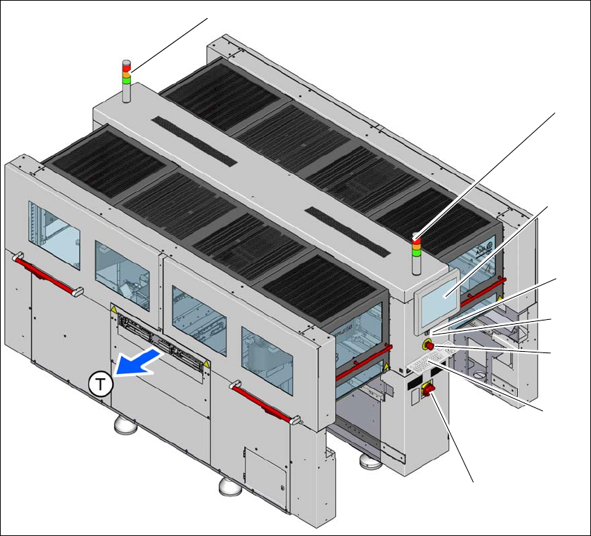
5.2 Controls and displays
5.2.1 Overview
5
Fig. 5.2 - 1 Controls and displays
(1) Main switch (5) Start button (white)
(2) Stop button (black) (6) LCD touchscreen
(3) EMERGENCY STOP button (7) Indicator lamps with buzzer
(4) Keyboard (optional) (T) Direction of PCB conveyor
(1)
(2)
(3)
(5)
(6)
(7)
(7)
(4)