00198382-03_UM_SIPLACE-CA4-V2_EN.pdf - 第267页
Instruction manual SIPLACE CA4 V2 6 Component handling From software version 713.0 Edition 12/2019 6.2 Component trolley 267 6.2.1 Structure The component trolley essentially consist s of the chassis, the changeover tabl…
6 Component handling Instruction manual SIPLACE CA4 V2
6.2 Component trolley From software version 713.0 Edition 12/2019
266
6
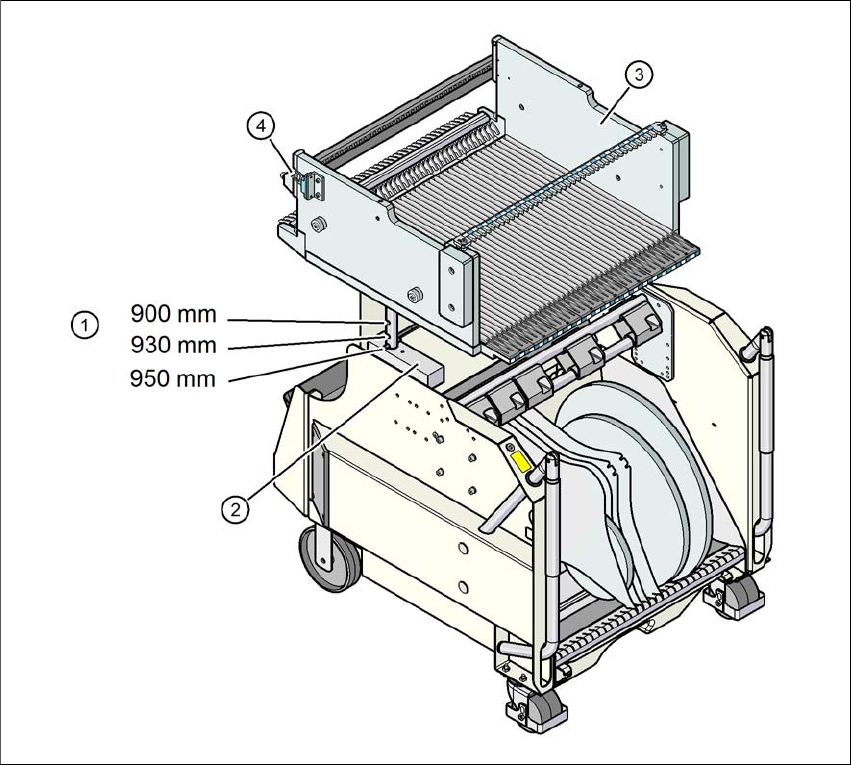
Fig. 6.2 - 2 Component trolley, SIPLACE X-Series, with a PCB conveyor height of 950 mm
6
(1) Holes in the guide columns for the PCB conveyor heights of 900, 930 and 950 mm.
(2) Support block
(3) Changeover table
(4) Contact for switching the safety switch in the COT insert
Instruction manual SIPLACE CA4 V2 6 Component handling
From software version 713.0 Edition 12/2019 6.2 Component trolley
267
6.2.1 Structure
The component trolley essentially consists of the chassis, the changeover table for holding the
feeder modules, the tape reel container and the waste tape container.
6
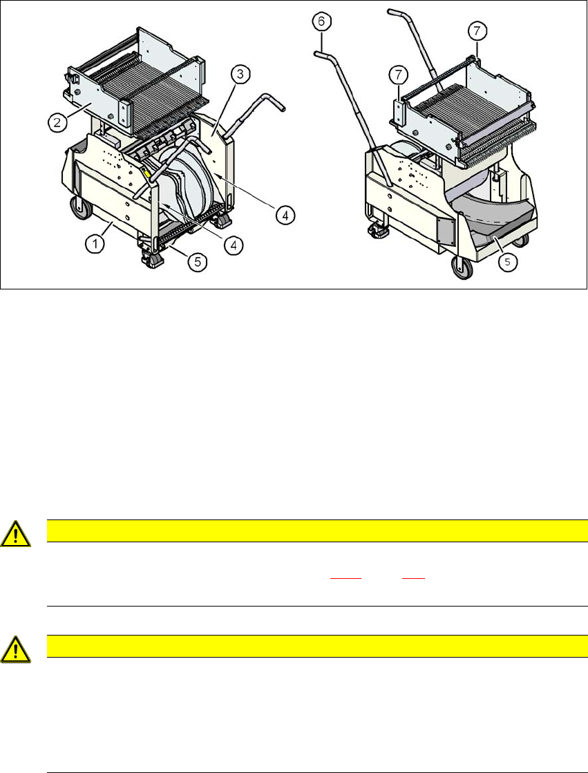
Fig. 6.2 - 3 Component trolley, SIPLACE X-Series, front and rear view
(1) Chassis
(2) Changeover table
(3) Tape container
(4) Gap for accommodation of setup lists
(5) Waste tape container
(6) Handle
(7) Hand guard
6
6
CAUTION
Observe the safety instructions!
Observe the safety instructions in section 5.8.2, page 221 when you pull the tape re-
ject bin out of the component trolley.
CAUTION
Risk of breaking handles!
Risk of breaking handles when transporting the component trolley.
When transporting the component trolley, do not lift it by its handles.
Only use the handles to push the component trolley.
Use a fork-lift if you want to conveyor the component trolley or lift it off the pallet.
6 Component handling Instruction manual SIPLACE CA4 V2
6.2 Component trolley From software version 713.0 Edition 12/2019
268
6.2.2 Description
In the standard version, the tape reel container (item 3 in fig. 6.2 - 3) holds tape reels up to a size
of 17" (432 mm).
There are two 5 mm wide gaps on the left and right, between the tape container and the compo-
nent trolley (item. 4 in fig. 6.2 - 3
, page 267) for holding setup lists.
The pullout waste tape container can be found beneath the chassis (item 5 in fig. 6.2 - 3
, page
267
). The cut waste tape travel down a chute into the waste tape container, which must be emptied
as it fills up.
The handles (item 6 in fig. 6.2 - 3
, page 267) can be folded up or down.
6
PLEASE NOTE
All component trolleys must be docked onto the
placement machine in order to operate it.
Fill any free locations with dummy feeder modules as described in
section 2.6.5
, page 83.