00198382-03_UM_SIPLACE-CA4-V2_EN.pdf - 第293页
Instruction manual SIPLACE CA4 V2 7 Station extensions From software version 713.0 Edition 12/2019 7.2 Vacuum pump 293 7.2 V acuum pump The vacuum pump s for the head supply and vacuum tooling (if pre sent) are locate d …
7 Station extensions Instruction manual SIPLACE CA4 V2
7.1 Nozzle changer From software version 713.0 Edition 12/2019
292
Place the magazine on the snap fastener balls (item 5 in fig. 7.1 - 9, page 291).
Press the magazine down evenly so that the snap fastener balls engage in all the snap fas-
teners at the same time.
7.1.3.3 Position detection
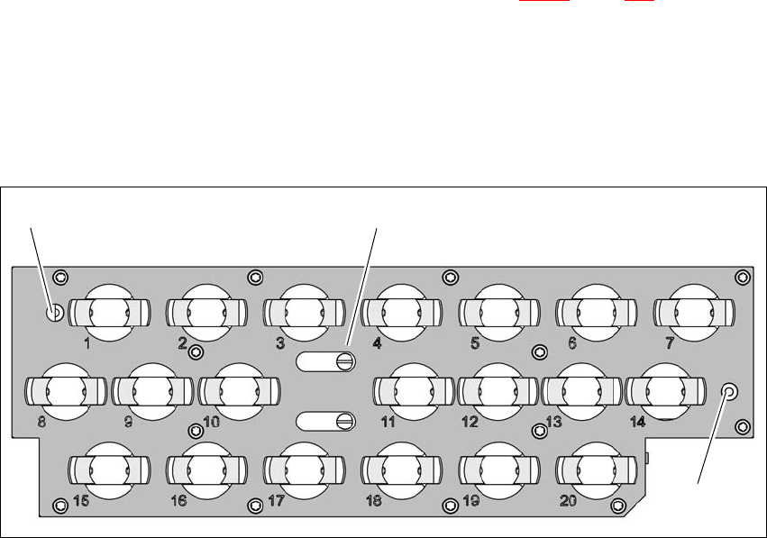
Each nozzle changer magazine has two fiducials for determining the position.
7
Fig. 7.1 - 10 Nozzle magazine - holder numbering, fiducials for determining the position and angular position
(1) Locking plate in the "magazine open" position
(2) Fiducials for determining the position
(1)
(2)
(2)
Instruction manual SIPLACE CA4 V2 7 Station extensions
From software version 713.0 Edition 12/2019 7.2 Vacuum pump
293
7.2 Vacuum pump
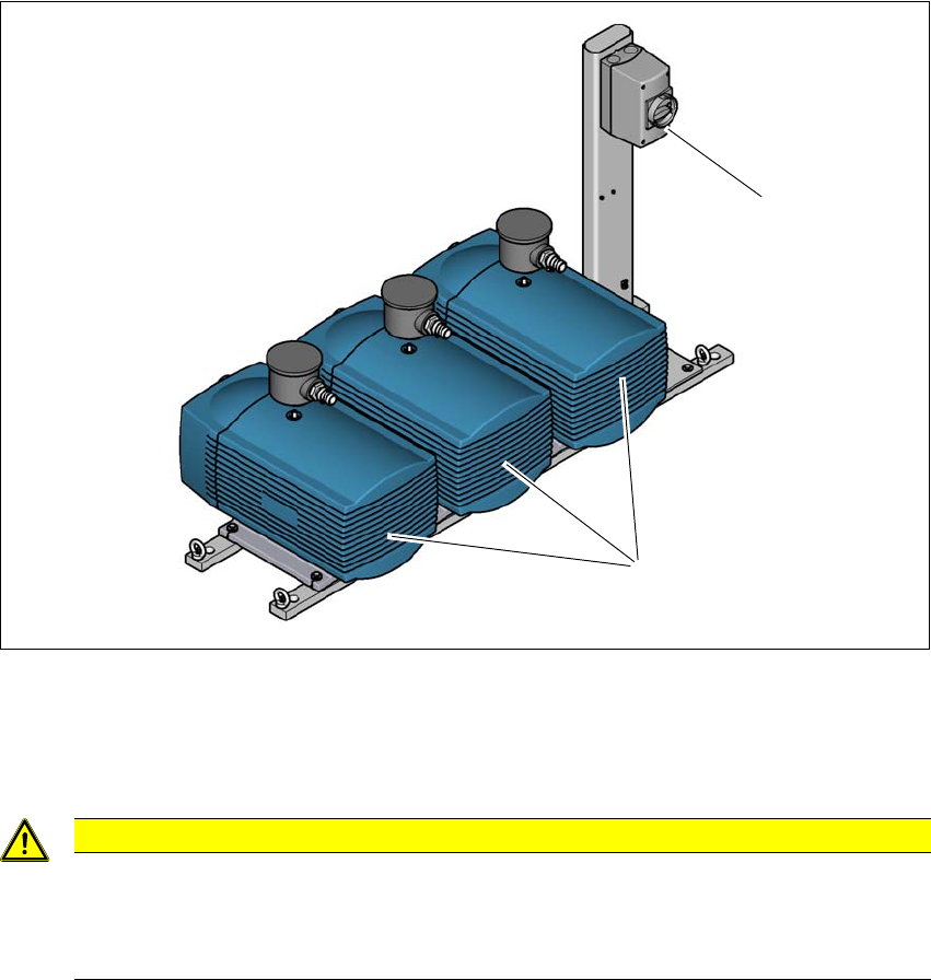
The vacuum pumps for the head supply and vacuum tooling (if present) are located on a frame
next to the placement machine. This frame is also used as an earthquake anchor and can be
screwed into the ground. The vacuum pumps for the heads are controlled by the placement ma-
chine and can only be switched off via the placement machine. The vacuum tooling vacuum pump
has its own switch and bypass valve.
7.2.1 Overview
7
Fig. 7.2 - 1 Overview - vacuum pumps on rack
(1) Vacuum pumps (2x head supply and 1x vacuum tooling)
(2) Switch for the vacuum tooling vacuum pump
7
7
CAUTION
Vacuum pumps next to the placement machine
If the vacuum pumps are next to the placement machine or outside the placement ma-
chine installation location (clean room operation), the customer will need to perform a
hazard assessment and make sure that the operation of these pumps is safe.
(1)
(2)

7 Station extensions Instruction manual SIPLACE CA4 V2
7.2 Vacuum pump From software version 713.0 Edition 12/2019
294
7.2.2 Safety instructions for vacuum pumps
All the following measures are to be observed during service work to the vacuum pumps:
– Service work may only be performed by trained service personnel
– Both the main switch for the placement machine and the main switch for the vacuum tooling
vacuum pump (item 2 in the fig. 7.2 - 1
, page 293) are to be secured in the OFF position with
a padlock, to prevent unauthorized activation.
– Both the CEE connector for the SIPLACE CA4 V2 and the CEE connector for the vacuum
pump of the vacuum tooling are to be unplugged from the mains supply.
– Unplug the connector for the motor cable (ILME connector) at all three vacuum pumps. These
connectors are at a maximum of 1.6m away from the pumps and are therefore visible to the
service engineer.
7
7.2.3 Description
Each Collect&Place head has its own vacuum generator, which supplies the holding and place-
ment circuit with the required vacuum. The vacuum generator for the placement heads functions
according to the Venturi principle. When operated together with a vacuum pump, the compressed
air consumption for the SpeedStar (C&P20 M2) head can be reduced considerably. A vacuum
pump can supply up to two SpeedStar (C&P20 M2) heads. A maximum of two vacuum pumps can
therefore be used (for 4x C&P20 M2). The running costs will fall according to the energy costs
incurred.
The vacuum pump is switched on and off with the placement machine. The station software auto-
matically takes a runoff time of 6 minutes into consideration at switch off.
7
7.2.4 Maintenance instructions
Observe the additional maintenance instructions for the vacuum pump.
Read the relevant section in the maintenance manual for your placement machine.
WARNING
Please observe the safety instructions in the manufacturer's instruction manual sup-
plied.
PLEASE NOTE
The compressed air consumption values can be found in section 3.2.4
, page 102.