00198382-03_UM_SIPLACE-CA4-V2_EN.pdf - 第202页
5 Tasks at the placement machine Instruction manual SIPLACE CA4 V2 5.4 Switching the SIPLACE CA4 V2 off From software version 713.0 Edition 12/2019 202 5.4 Switching the SIPLACE CA4 V2 off 5 5.4.1 Switching off the st at…
Instruction manual SIPLACE CA4 V2 5 Tasks at the placement machine
From software version 713.0 Edition 12/2019 5.3 Switching the SIPLACE CA4 V2 on
201
5.3.4 Action of placement machine start button
The action performed by the start button can be set.
Open the "Check sensors and functions" view (see section 5.5.3, page 205).
The following settings are possible:
Start production automatically 5
Standard setting.
Pressing the start button automatically begins the production process.
Do not change production status 5
This is used, for example, to calibrate and test the placement machine
Pressing the start button simply closes the electricity circuit; production is not started immediately.
5
CAUTION
Machine functions can be directly started via the GUI, irrespective of the start button set-
ting. If the electrical circuit has already been closed, you do not need to confirm with the
placement machine start button.
5 Tasks at the placement machine Instruction manual SIPLACE CA4 V2
5.4 Switching the SIPLACE CA4 V2 off From software version 713.0 Edition 12/2019
202
5.4 Switching the SIPLACE CA4 V2 off
5
5.4.1 Switching off the stations
To switch off the stations, proceed as follows:
End all placement procedures, so that there are no more boards in the placement machine.
Check whether the Z axes of all placement heads are in their uppermost end positions.
Check whether there are still components on the placement heads and remove these.
Close the station computer software in the view
Settings --> Machine Settings --> Shut Down Machine...
Once the computer has been shut down, switch off the station at the main switch.
CAUTION
Before you switch off the station, observe the following procedures.
Instruction manual SIPLACE CA4 V2 5 Tasks at the placement machine
From software version 713.0 Edition 12/2019 5.5 The user interface
203
5.5 The user interface
The user interface is divided into the following areas.
5
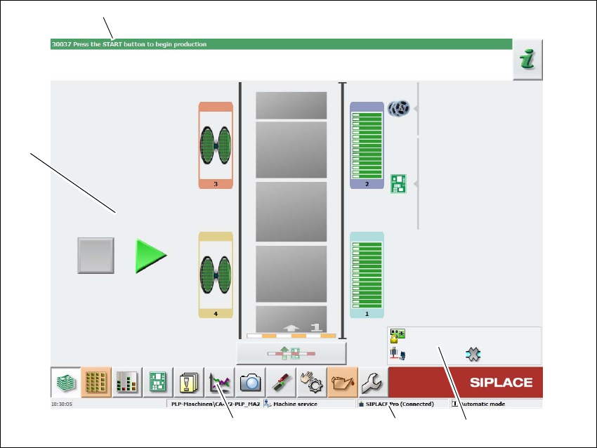
Fig. 5.5 - 1 User interface components in the "Production" view (example)
Legend
(1) Status field (status and error display)
(2) Processing area / display area
(3) Toolbar
(4) Information line
(5) View of changed configurations and additional options e.g. barcode mode
(1)
(2)
(3)
(4)
(5)