00198382-03_UM_SIPLACE-CA4-V2_EN.pdf - 第253页
Instruction manual SIPLACE CA4 V2 6 Component handling From software version 713.0 Ed ition 12/2019 6.1 SIPLACE tape feed er modules for SIPLACE CA4 V2 253 6.1.2 Linear Dipping Unit 2 X ( LDU 2 X) Item no. 001 17012-xx L…

6 Component handling Instruction manual SIPLACE CA4 V2
6.1 SIPLACE tape feeder modules for SIPLACE CA4 V2 From software version 713.0 Edition 12/2019
252
6.1.1.5 Technical data for SIPLACE tape feeder modules
In general, the SIPLACE tape feeder modules have a length of approx. 587 mm and a height of
approx. 200 mm. The technical data are listed in the following table.
The maximum height of the interference contours above the upper edge of the tape pocket is
3 mm. As the SIPLACE tape feeder modules do not show any flaps projecting upwards and are
also fixed to the changeover tables, the risk of a head crash is reduced to a minimum.
Tape feeder module L x H
[mm]
Width
[mm]
Location
occupied
Conveyor
increment
[mm]
Max. tape
height
[mm]
*a
SIPLACE SmartFeeder 4 mm Xi 587x200 10.8 1 1 1.1
With splice sensor
SIPLACE SmartFeeder 8 mm X 587x200 10.8 1 1/2/4/8 3.5
With splice sensor
SIPLACE SmartFeeder 8 mm Xi 587x200 10.8 1 1/2/4/8 3.5
With splice sensor
SIPLACE SmartFeeder 2x8 mm Xi 587x200 22.6 2 1/2/4/8 3.5
With splice sensor
SIPLACE SmartFeeder 12 mm X 587x200 22.6 24 - 16
*b
6.5
With splice sensor
SIPLACE SmartFeeder 16 mm X 587x200 22.6 2 4 - 20
*b
25
With splice sensor
SIPLACE SmartFeeder 24 mm X
587x200 34,4 3 4 - 32
*b
25
With splice sensor
SIPLACE SmartFeeder 32 mm Xx
587x200 46,2 4 4 - 40
*b
25
With splice sensor
SIPLACE SmartFeeder 44 mm X
587x200 58.0 5 4 - 52
*b
25
With splice sensor
SIPLACE SmartFeeder 56 mm X
587x200 69,8 64 - 64
*b
25
With splice sensor
SIPLACE SmartFeeder 72 mm X
587x200 81.6 7 4 - 80
*b
25
With splice sensor
SIPLACE SmartFeeder 88 mm X
587x200 105,2 9 4 - 96
*b
25
With splice sensor
SIPLACE SmartFeeder 104 mm X
587x200 128,9 11 4 - 96
*b
25
With splice sensor
Tape reels 178 to max. 483 mm diameter (7“ - 19“)
Changeover time 8 s
*)a For 8 mm paper tapes, the paper thickness must not exceed 1.6 mm. The length of a component pocket in the
direction of tape travel may not exceed 51 mm.
*)b In 4mm steps
Instruction manual SIPLACE CA4 V2 6 Component handling
From software version 713.0 Edition 12/2019 6.1 SIPLACE tape feeder modules for SIPLACE CA4 V2
253
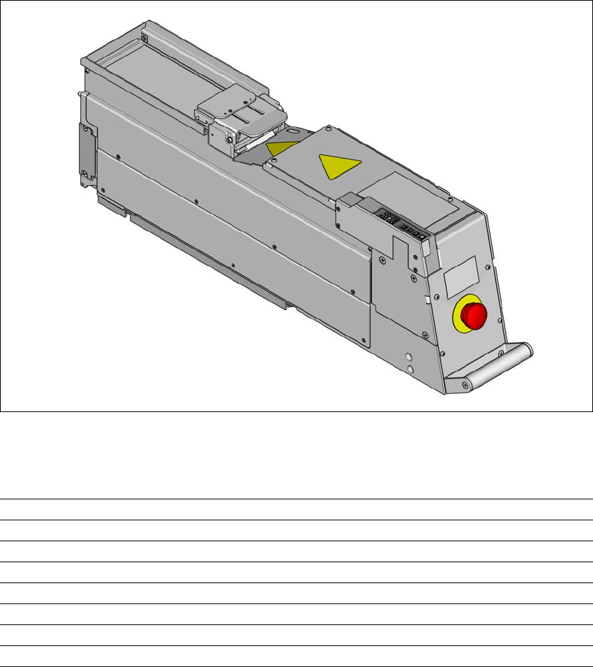
6.1.2 Linear Dipping Unit 2 X ( LDU 2 X)
Item no. 00117012-xx Linear dip module for flux / LDU 2 X
The LDU 2 X is a special feeder module, which can make flux available with a defined layer thick-
ness. This flux can be used to coat components, thereby improving their solder properties. The
LDU 2 X is set up on the changeover table in the same way as an X feeder module and is con-
trolled via the station software and line software.
For a detailed description, refer to the user guide "SIPLACE LDU 2 X".
6
Fig. 6.1 - 3 Linear Dipping Unit (LDU 2 X)
6.1.2.1 Technical data
Dimensions (L x W x H) 629 mm x 105 mm x 202 mm
Weight 11 kg
Current consumption 24 V dc bis 30 V dc, 2 A (60 W)
Max. noise emissions 61dB (A)
Temperature range (storage) Between -25°C and +55°C
Temperature range (operation) Between +18°C and +25°C
Humidity (storage) ≤ 95%
Humidity (operation) 30% - 75% (on average not > 45%)

6 Component handling Instruction manual SIPLACE CA4 V2
6.1 SIPLACE tape feeder modules for SIPLACE CA4 V2 From software version 713.0 Edition 12/2019
254
6.1.3 Feeder module adapter for the X-Series
Item no. 00141305-xx Adapter for X-Series feeder modules
Item no. 00141308-xx Adapter plate for reject conveyor
Item no. 00141310-xx Adapter plate for label presenter
6
The spectrum of X tape feeder modules has been extended to include the linear vibratory feeder,
the label presenter and the reject conveyor. With an adapter, you can also convert the S linear
vibratory feeder, label presenter and reject conveyor for use with CA4 V2 component trolleys. The
adapter performs electronic as well as mechanical functions: It converts the communication sig-
nals from the S feeder modules into signals conforming to the extended X-Series protocol. Addi-
tional functions, such as feeder module identification, have also been implemented.
6
PLEASE NOTE
S linear vibratory feeders, label presenters and reject conveyors can not be set up at
component trolleys if these are in the access range of a SpeedStar (C&P20).