00198382-03_UM_SIPLACE-CA4-V2_EN.pdf - 第18页
1 Introduction Instruction manual SIPLACE CA4 V2 1.2 Placement machine description From software version 713.0 Edi tion 12/2019 18 The CA4 V2 has four gan tries, two for each p lacement a rea (P A). All the gantry axes a…
Instruction manual SIPLACE CA4 V2 1 Introduction
From software version 713.0 Edition 12/2019 1.2 Placement machine description
17
1.2 Placement machine description
1.2.1 SIPLACE CA4 V2
1
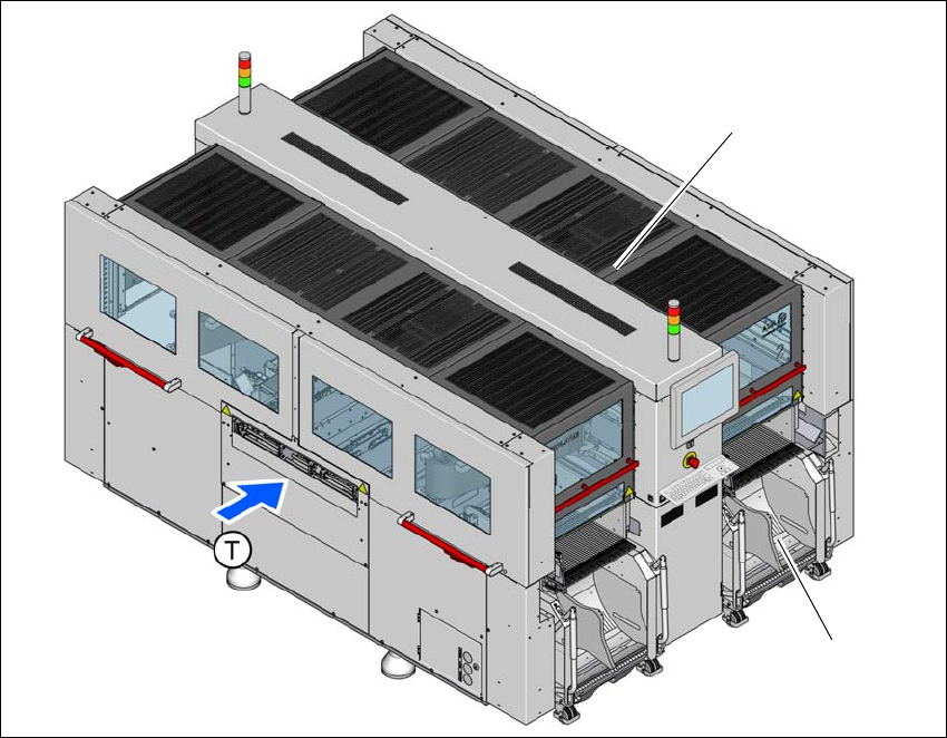
Fig. 1.2 - 1 SIPLACE CA4 V2 placement machine
(1) SIPLACE CA4 V2
(2) Component trolley at location 2
(T) Direction of PCB conveyor
The SIPLACE CA4 V2 impresses with high configuration flexibility, top placement performance
and maximum precision. The SIPLACE CA4 V2 can place bare dies directly from the wafer, in the
flip chip or die attach process. It also supports placement of the SMT spectrum used with the SI-
PLACE X4 S in conjunction with the relevant placement heads.
Two placement methods are used on the placement machines:
– The Collect&Place method for high-speed placement of standard components
– The Pick&Place method with the CPP M in Pick&Place mode, for fast placement of special
components in the fine-pitch and super fine-pitch range
(1)
(2)
1 Introduction Instruction manual SIPLACE CA4 V2
1.2 Placement machine description From software version 713.0 Edition 12/2019
18
The CA4 V2 has four gantries, two for each placement area (PA). All the gantry axes are driven
by linear motors. The gantry axes can be positioned quickly and accurately in the X and Y direc-
tions. Each gantry has one placement head. The gantry arms are lightweight constructions made
from a highly rigid carbon fiber composite material.
The SIPLACE CA4 V2 is based on the successful hardware and software platform from the SI-
PLACE X4 S.
The SIPLACE CA4 V2 facilitates a placement accuracy of up to 10 µm at 3
. The following com-
ponents from the SIPLACE CA4 V2 are used:
– SIPLACE SpeedStar C&P20 M2
– SIPLACE MultiStar CPP M
– High-resolution glass scales on the X and Y axis
– Highly rigid board conveyor
– Single lane conveyor
– Dual lane conveyor
– Panel lane conveyor with optional vacuum tooling
– Wafer lane conveyor with optional vacuum tooling
– Optional fiducial rail in X direction for cyclical calculation of the placement machine
Instruction manual SIPLACE CA4 V2 1 Introduction
From software version 713.0 Edition 12/2019 1.2 Placement machine description
19
1.2.2 Wafer and panel level fan out process
1.2.2.1 Panel level fan out process
Panel level fan out is used for large workpiece carriers. A double-sided thermal release foil is
attached to a workpiece carrier (e.g. made of steel or glass) and placement is performed on this.
The panel level fan out mode means that part of the workpiece carrier is placed in the first place-
ment area and the remaining part in the second placement area. To achieve the required accu-
racy, the fiducials on the workpiece carrier are only used for rough position recognition. These
fiducials for rough position searching must be within an overlapping area. Two are enough. Four
components with fiducial structures are then placed in this overlapping area and measured for fine
position recognition purposes. Other possible or required fiducials are then placed as references,
in addition to the fiducials already placed. In the second placement area, the four fiducials already
placed are measured first, before proceeding as in the first placement area.
1
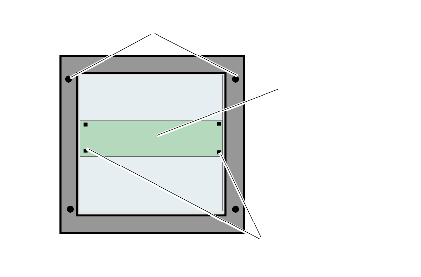
Fig. 1.2 - 2 Sketch of panel level fan out
Fiducials for rough position recognition on the workpiece
carrier (rough position)
Overlapping area
Components placed for measuring the fine position.