00198382-03_UM_SIPLACE-CA4-V2_EN.pdf - 第133页
Instruction manual SIPLACE CA4 V2 3 Technical data and assemblie s From software version 713.0 Ed ition 12/2019 3.7 PCB conveyor syst em 133 3.7.5.1 Import ant information about the temperature control syst em 3 3 WARNIN…
3 Technical data and assemblies Instruction manual SIPLACE CA4 V2
3.7 PCB conveyor system From software version 713.0 Edition 12/2019
132
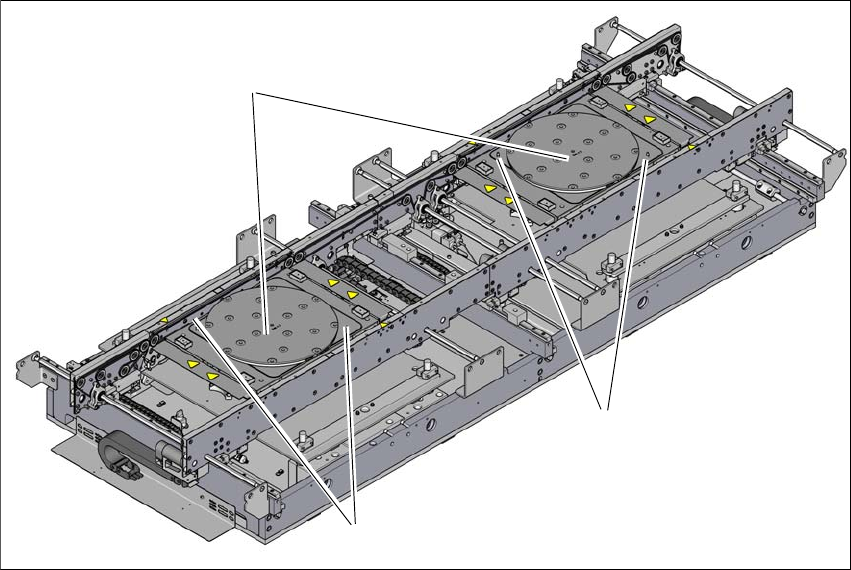
3.7.5 Wafer lane conveyor
There are two different vacuum tooling options for the different workpiece carrier thicknesses
available for the Wafer lane conveyor:
– DM 300 ST 0.55 for thin workpiece carriers
– DM 300 ST 1.2 for thick workpiece carriers
The vacuum tooling DM 300 can be temperature-controlled. The corners feature glass fiducials to
compensate the precise position of the vacuum tooling in the placement machine and the defor-
mation of the placement machine.
A temperature regulating system to keep the set process temperature constant is available for the
temperature-controlled vacuum tooling.
Item no. 0051979-xx Wafer lane conveyor vario
Item no. 03160190-xx Vacuum tooling DM 300 ST 0.5
Item no. 03161016-xx Vacuum tooling DM 300 ST 1.2
Item no. 03133161-xx Temperature control system fluid
3
Fig. 3.7 - 7 Wafer lane conveyor with vacuum tooling DM 300
(1) Vacuum tooling DM 300
(2) Glass fiducials
(1)
(2)
(2)
Instruction manual SIPLACE CA4 V2 3 Technical data and assemblies
From software version 713.0 Edition 12/2019 3.7 PCB conveyor system
133
3.7.5.1 Important information about the temperature control system
3
3
WARNING
Recommended fluids
The only medium which may be used for the temperature control system
is Novec
7500
TM
.
When handling this medium, observe the manufacturer's product information and
data sheets.
PLEASE NOTE
Description and operation of temperature control system
The safety instructions, description and operation instructions for the temperature control
system can be found in the manufacturer's instruction manual "Grande Fleur
®
/ Petite
Fleur
®
" supplied.

3 Technical data and assemblies Instruction manual SIPLACE CA4 V2
3.7 PCB conveyor system From software version 713.0 Edition 12/2019
134
3.7.6 Technical data
3.7.6.1 Single lane and dual lane conveyor
3
Single lane conveyor Dual lane conveyor Dual lane conveyor in
"single lane con-
veyor" mode
Board dimensions
(length x width)
Standard 50 mm x 50 mm to
450 mm x 685 mm
*a
50 mm x 50 mm to
450 mm x 320 mm
50 mm x 50 mm to
450 mm x 600 mm*
b
Long board
*b
50 mm x 50 mm to
850 mm x 685 mm*
b
50 mm x 50 mm to
850 mm x 320 mm
50 mm x 50 mm to
850 mm x 600 mm*
b
Stationary conveyor side Right or left Right, left or outer
Automatic electrical width adjustment Standard
PCB thickness
Standard 0.3
*c
mm to 4.5 mm
PCB warpage See page 136
PCB weight
*d
Max. 10.0 kg
*e
Max. 2.0 kg Max. 2.0 kg
Clearance on PCB underside 25 mm
PCB conveyor height
Option
Standard
Option SMEMA
900 mm
930 mm
950 mm
Type of interface SMEMA or IPC-HERMES-9852
Component-free PCB handling edge 3 mm
PCB changeover time
Single lane conveyor
Dual lane conveyor
*f
< 1.5 seconds
0 seconds
*)a PCB width up to 560 mm as default. PCB widths up to 685 mm available on request.
*)b With input and output conveyor extension only.
*)c Thinner than 0.3 mm on request
*)d The board weight value refers to the weight of the board plus the weight of the components.
*)e Default 3.0 kg. PCB weight up to 10.0 kg available on request.
*)f 0 seconds in asynchronous mode, otherwise 1.5 seconds.