00198382-03_UM_SIPLACE-CA4-V2_EN.pdf - 第203页
Instruction manual SIPLACE CA4 V 2 5 Tasks at the placement machi ne From software version 713.0 Ed ition 12/2019 5.5 The user interfac e 203 5.5 The user interface The user interface is divided into the following areas.…
5 Tasks at the placement machine Instruction manual SIPLACE CA4 V2
5.4 Switching the SIPLACE CA4 V2 off From software version 713.0 Edition 12/2019
202
5.4 Switching the SIPLACE CA4 V2 off
5
5.4.1 Switching off the stations
To switch off the stations, proceed as follows:
End all placement procedures, so that there are no more boards in the placement machine.
Check whether the Z axes of all placement heads are in their uppermost end positions.
Check whether there are still components on the placement heads and remove these.
Close the station computer software in the view
Settings --> Machine Settings --> Shut Down Machine...
Once the computer has been shut down, switch off the station at the main switch.
CAUTION
Before you switch off the station, observe the following procedures.
Instruction manual SIPLACE CA4 V2 5 Tasks at the placement machine
From software version 713.0 Edition 12/2019 5.5 The user interface
203
5.5 The user interface
The user interface is divided into the following areas.
5
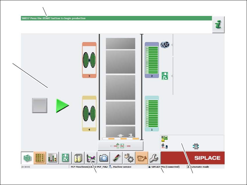
Fig. 5.5 - 1 User interface components in the "Production" view (example)
Legend
(1) Status field (status and error display)
(2) Processing area / display area
(3) Toolbar
(4) Information line
(5) View of changed configurations and additional options e.g. barcode mode
(1)
(2)
(3)
(4)
(5)
5 Tasks at the placement machine Instruction manual SIPLACE CA4 V2
5.5 The user interface From software version 713.0 Edition 12/2019
204
5.5.1 Status field
The status field shows the current machine status, the error which occurred most recently and the
action to be performed.
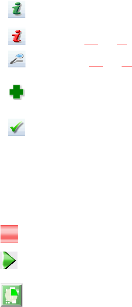
The right-hand side of the status field shows the status with the following icons:
(Green) Starts the context-sensitive Online Help function for the current view. All operating con-
trols for the current view are explained
(Red) Starts the help system, showing the possible causes of the current errors and suitable solu-
tions (see section 5.6.2
, page 212).
Opens a dialog box in which the error source, error message text and the error date with time are
shown (see section 5.6.3
, page 213). The help function for the current error can also be opened
from here.
Opens a detailed view for the current error. Troubleshooting measures can be directly opened
from this view (only shown for certain error messages).
Deletes the error currently shown from the status field.
5.5.2 Display and processing area
This area shows the buttons for setting/deleting functions, general information about the board,
setup, recipes and other information.
Animated and color-coded items helps explain processes or states (e.g. editing, empty location
etc.).
The "Production" (basic view) view indicates certain operating states (editing, error etc.).
Stop processing. This stops the current processing run.
Continue processing. This starts or continues board placement.
Progress
The placement progress is shown in the diagram view for each board.