00198382-03_UM_SIPLACE-CA4-V2_EN.pdf - 第67页
Instruction manual SIPLACE CA4 V2 2 Operational safety From software version 713.0 Edition 12/2019 2.5 Safety instructio ns for operation 67 2.5.7 Safety instructions f or using the nozzle changer Observe the following i…

2 Operational safety Instruction manual SIPLACE CA4 V2
2.5 Safety instructions for operation From software version 713.0 Edition 12/2019
66
The ambient conditions are unfavorable if:
(1) The components remain on the tape while the set tape cycle is checked (since the operator
can cycle the feeder module onward without removing components during this check).
(2) The components remain on the tape, e.g. due to a tear in the cover foil.
(3) The components remain on the tape, and the components or tape do not conform to the spec-
ification, thus increasing the pickup error rate.
Please follow the instructions given below to minimize the risk when placing capacitors based on
powdered metal.
(1) If the component tape is cycled onward manually, the operator must remove any components
remaining in the tape pocket.
(2) If the cover foil tears, the operator must remove any components remaining on the tape.
To prevent tantalum capacitors which were not picked up from causing the tape material to burn
when it is cut, the user interface has been extended to include the option "Stop immediately on
pickup error". This option must be enabled in SIPLACE Pro. On the placement machine, the com-
ponent that was not picked up is paced forward again until it is ready for removal from the com-
ponent tape. The track is deactivated and the operator is sent an error message to remind him to
pick up the tantalum component from the tape.
2
2.5.5 ESD safety of placement machine
Only use nozzles that are identified as conductive. This is the only way to meet the requirements
for the ESD safety of the placement machine.
2.5.6 Safety instructions for correct fitting of the reject bin
Observe the following instructions to avoid risk of collision between the placement head and com-
ponent or the nozzle reject bin:
Make sure, that the reject bin is seated correctly in its mount.
Check that the reject bin does not project over the mount.
2
PLEASE NOTE
Manual removal of tantalum capacitors not picked up
The manual removal by the operator of tantalum capacitors which were not picked up is
described in section 6.1.1.2
, page 249 .
PLEASE NOTE
A sensor (see section 7.9
, page 303) which indicates the correct position of the reject bin
can be retrofitted for each reject bin.

Instruction manual SIPLACE CA4 V2 2 Operational safety
From software version 713.0 Edition 12/2019 2.5 Safety instructions for operation
67
2.5.7 Safety instructions for using the nozzle changer
Observe the following instructions to avoid risk of collision between the placement head and the
nozzle changer.
2
2
WARNING
Risk of head crashes with mixed configurations!
There is a risk of head crashes with mixed configurations.
Only install the corresponding nozzle changer for each placement head, with the
nozzle magazines for the respective placement head.
WARNING
Risk of head crashes with protruding lever!
A lever which projects above the magazine could lead to a placement head crash.
You should therefore make sure that the lever does not protrude over the maga-
zines.
2 Operational safety Instruction manual SIPLACE CA4 V2
2.5 Safety instructions for operation From software version 713.0 Edition 12/2019
68
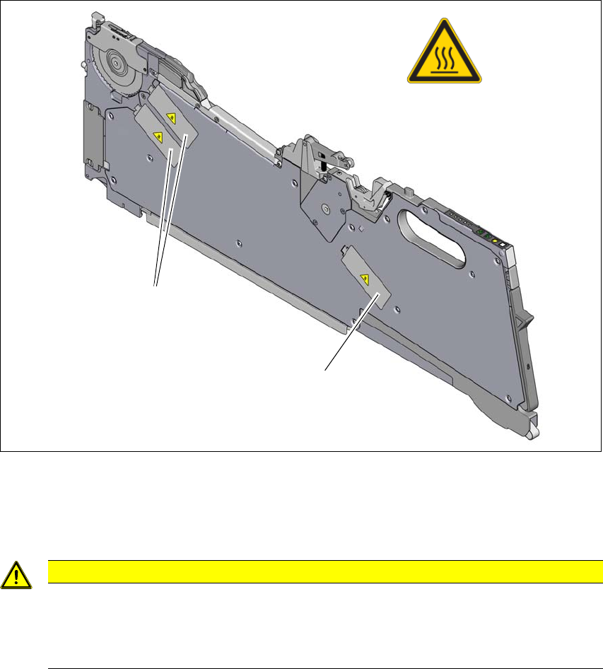
2.5.8 High temperatures on the X feeder modules during continuous operation
2
Fig. 2.5 - 3 High temperatures on the X feeder modules during continuous operation
(1) Temperature sign, item no. 03031926-01
(2) Stepping motor
2
2
CAUTION
Risk of burns due to high temperatures!
The stepping motors can become very hot during continuous operation and in an ambient
temperature in excess of 22 °C.
Be careful when touching the motors.
(1)
(2)
(2)