00198382-03_UM_SIPLACE-CA4-V2_EN.pdf - 第275页
Instruction manual SIPLACE CA4 V2 6 Component handling From software version 713.0 Edition 12/2019 6.2 Component trolley 275 6.2.8 T ape cont ainer 6.2.8.1 Description The tape co ntainer ca n hold reel s up to 19" …
6 Component handling Instruction manual SIPLACE CA4 V2
6.2 Component trolley From software version 713.0 Edition 12/2019
274
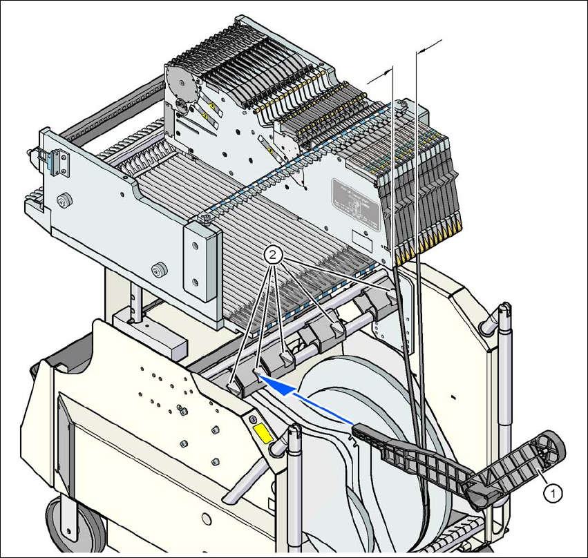
6.2.7 Mount of additional tape reel
6
Fig. 6.2 - 8 Mount of additional tape reel
(1) Mount of additional tape reel, item no. 00141217-xx
(2) Mounting device for the support
X-Series feeder modules can process component tapes without problems if the lateral offset be-
tween the feeder module and the tape reel does not exceed 60 mm. If a predefined setup means
that the maximum permitted offset cannot be maintained, we recommend that you use the mount
for an additional tape reel (item 1). Simply insert the mount into the holder (item 2) and push it until
the offset is less than the maximum permitted value of 60 mm. The component trolley has 5 hold-
ers in total. Each tape reel mount can hold 2 tape reels, which means that up to ten 15" (381 mm)
reels can be positioned above the tape container.
Max. 60 mm
Instruction manual SIPLACE CA4 V2 6 Component handling
From software version 713.0 Edition 12/2019 6.2 Component trolley
275
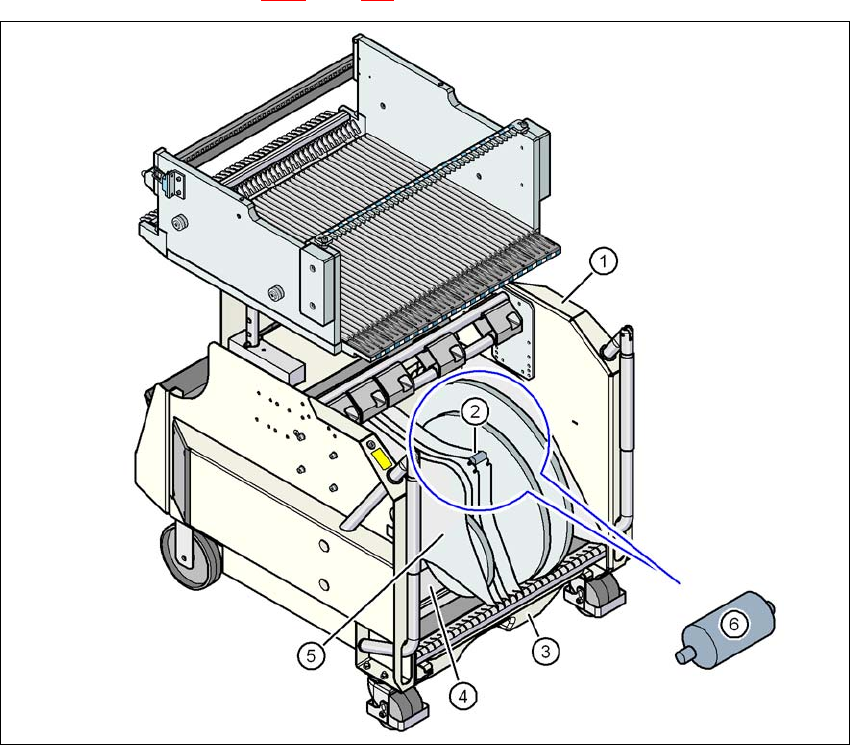
6.2.8 Tape container
6.2.8.1 Description
The tape container can hold reels up to 19" (483 mm) in diameter. The insertion of separating
plates is described in section 5.9.5
page 225.
6
Fig. 6.2 - 9 Component trolley, with tape container
(1) Component trolley
(2) Position of spindles
(3) Waste tape container
(4) Tape container
(5) Separating plate
(6) Spindle (zoom)
6 Component handling Instruction manual SIPLACE CA4 V2
6.2 Component trolley From software version 713.0 Edition 12/2019
276
6.2.8.2 Maximum tape reel diameter in relation to the PCB conveyor height
6
6
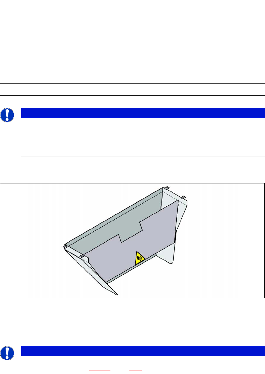
6.2.9 Used tape chute
6
Fig. 6.2 - 10 Used tape chute for the COT insert
In accordance with the PCB conveyor height, the length of the used tape chute can be set so that
the tape cuttings are directly diverted into the waste tape container of the component trolley.
6
Without mount for the
additional tape reel
With mount for the
additional tape reel
PCB conveyor
height
of the component
trolley
Tape reel diameter Tape reel diameter
without spindle with spindle
900 mm 19" 17" 15"
930 mm 19" 19" 17"
950 mm 19" 19" 19"
PLEASE NOTE
Using spindles
SIPLACE X-Series component trolleys do not generally need spindles.
Use spindles if the error message "Timeout" appears frequently on the X feeder
module.
PLEASE NOTE
The used tape chute for the CA4 V2 can only be installed on the COT insert
for the CA4 V2 (see fig. 5.15 - 3
, page 245).