00198382-03_UM_SIPLACE-CA4-V2_EN.pdf - 第177页
Instruction manual SIPLACE CA4 V2 4 Setting up and commissioning From software version 713.0 Ed ition 12/2019 4.3 Setting up the pl acement machine 177 4.3.7.1 Sp acing of machine feet for dual lane conveyor 4 Fig. 4.3 -…
4 Setting up and commissioning Instruction manual SIPLACE CA4 V2
4.3 Setting up the placement machine From software version 713.0 Edition 12/2019
176
4.3.7 Machine foot clearances and the stationary PCB conveyor edges
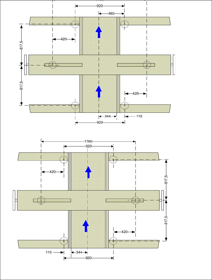
Spacing of machine feet for single lane conveyor
4
Fig. 4.3 - 8 Spacing of machine feet for single lane conveyor in millimeters
Fixed conveyor side at maximum
right position
a
.
a) The value depends on the position of the fixed side. All dimensions in millimeters.
Fixed conveyor side at maximum
left position
a
.
Instruction manual SIPLACE CA4 V2 4 Setting up and commissioning
From software version 713.0 Edition 12/2019 4.3 Setting up the placement machine
177
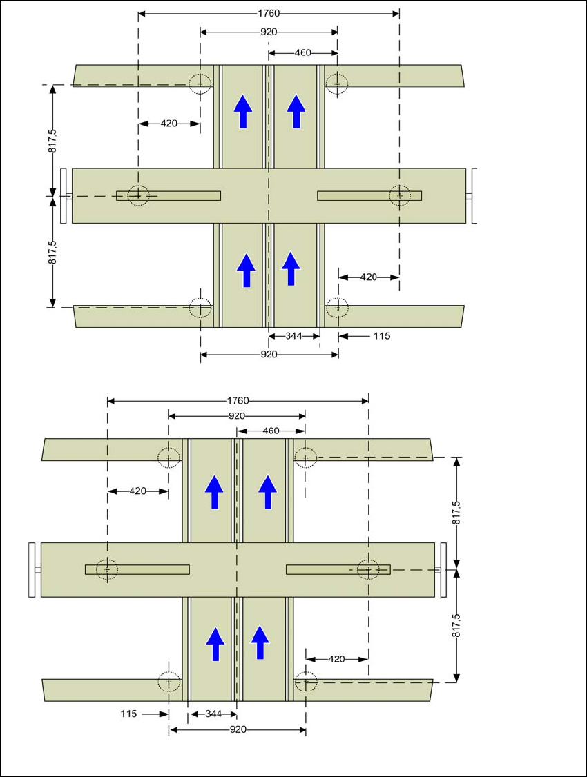
4.3.7.1 Spacing of machine feet for dual lane conveyor
4
Fig. 4.3 - 9 Spacing of machine feet for dual lane conveyor in millimeters
Fixed conveyor side at maxi-
mum right position
a
.
a) The value depends on the position of the fixed side. All dimensions in millimeters.
Fixed conveyor side at maxi-
mum left position
a
.
4 Setting up and commissioning Instruction manual SIPLACE CA4 V2
4.3 Setting up the placement machine From software version 713.0 Edition 12/2019
178
4.3.8 Integrating the placement machine into the line
Observe the general warnings in section 4.3.1, page 163.
Observe the warnings for transportation of the placement machine in section 4.3.2, page 164.
For details of tools and equipment, refer to section 4.3.5, page 167.
4.3.8.1 Aligning and adjusting the placement machines in the line
With the fork-lift, raise the placement machine until the weight is taken off the machine feet.
Determine the PCB conveyor height for the placement machine in the line and use the hexa-
gon socket head screw to adjust the height approximately.
You may need to fit the machine feet to the relevant PCB conveyor height (see 4.3.6 on page
168).
Position the placement machine on the free location on the line using the fork-lift.
Pay attention to the alignment of the PCB conveyors and check the distance to the previous
placement machine.
4
4
Align the placement machine in the X and Y direction with the help of the machine spirit level.
Place the machine spirit level in the X and then the Y direction on the sides of the conveyor
in placement area 1 (see fig. 4.3 - 10
). The board conveyor width has been preset:
Single lane conveyor 210 mm
Dual lane conveyor, lane 1 100 mm
Dual lane conveyor, lane 2 210 mm 4
4
Measure the distance between the upper edge of the PCB conveyor belt and the underside.
This distance should be 900 mm, 930 mm or 950 mm.
WARNING
Risk of damage!
If the machine feet on one side hit the ground hard, the fixings may be damaged.
Slowly lower the placement machine.
A second person should look underneath to ensure that all the machine foot touch
the floor at the same time.
PLEASE NOTE
When using the spirit level to adjust the dual lane conveyor in the X direction, always
place it on the outer edges of the placement machine.