00198382-03_UM_SIPLACE-CA4-V2_EN.pdf - 第20页
1 Introduction Instruction manual SIPLACE CA4 V2 1.2 Placement machine description From software version 713.0 Edi tion 12/2019 20 1.2.2.2 W afer level fan out W afer level fan out is used for smaller workpiece carriers …
Instruction manual SIPLACE CA4 V2 1 Introduction
From software version 713.0 Edition 12/2019 1.2 Placement machine description
19
1.2.2 Wafer and panel level fan out process
1.2.2.1 Panel level fan out process
Panel level fan out is used for large workpiece carriers. A double-sided thermal release foil is
attached to a workpiece carrier (e.g. made of steel or glass) and placement is performed on this.
The panel level fan out mode means that part of the workpiece carrier is placed in the first place-
ment area and the remaining part in the second placement area. To achieve the required accu-
racy, the fiducials on the workpiece carrier are only used for rough position recognition. These
fiducials for rough position searching must be within an overlapping area. Two are enough. Four
components with fiducial structures are then placed in this overlapping area and measured for fine
position recognition purposes. Other possible or required fiducials are then placed as references,
in addition to the fiducials already placed. In the second placement area, the four fiducials already
placed are measured first, before proceeding as in the first placement area.
1
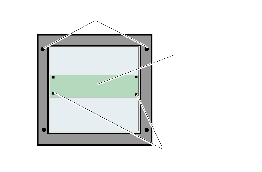
Fig. 1.2 - 2 Sketch of panel level fan out
Fiducials for rough position recognition on the workpiece
carrier (rough position)
Overlapping area
Components placed for measuring the fine position.
1 Introduction Instruction manual SIPLACE CA4 V2
1.2 Placement machine description From software version 713.0 Edition 12/2019
20
1.2.2.2 Wafer level fan out
Wafer level fan out is used for smaller workpiece carriers with different thicknesses. The vacuum
tooling used for this can be temperature-controlled. The wafer level fan out process can also be
used in conjunction with the Gas station mode.
In Gas station mode, two workpiece carriers are moved into the placement machine at the same
time.The first workpiece carrier is conveyed into the second placement area, the following work-
piece carrier to the first placement area. These two workpiece carriers are then clamped into place
at the same time. This prevents the clamping procedure from affecting the accuracy of the other
workpiece carrier. The two workpiece carriers are placed parallel to one another. One prerequisite
for Gas station mode, is that the setup in the first and second placement area is the same.
Instruction manual SIPLACE CA4 V2 1 Introduction
From software version 713.0 Edition 12/2019 1.2 Placement machine description
21
1.2.3 Placement machine serial number
The serial number of the placement machine can be found on the inside of the machine frame at
location 1.
1
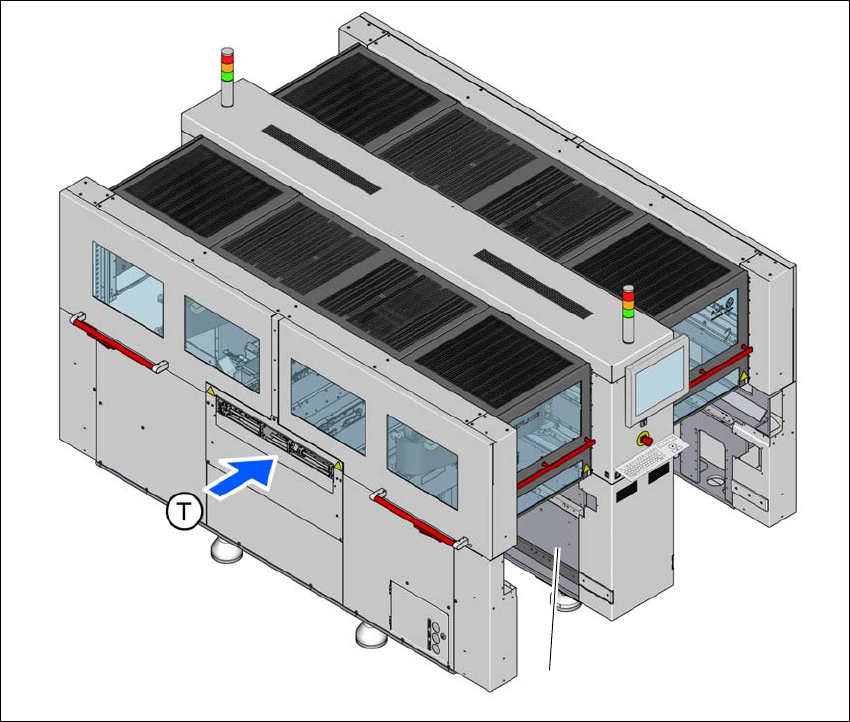
Fig. 1.2 - 3 Position of typeplate with serial number
(T) Direction of PCB conveyor
(1) Typeplate
(1)