00198382-03_UM_SIPLACE-CA4-V2_EN.pdf - 第110页
3 Technical data and assemblies I nstruction manual SIPLACE CA4 V 2 3.4 Overview of the modules From s oftware version 713.0 Edition 1 2/2019 110 3.4 Overview of the modules 3 3 Fig. 3.4 - 1 Overview of the modules (1) L…
Instruction manual SIPLACE CA4 V2 3 Technical data and assemblies
From software version 713.0 Edition 12/2019 3.3 Dimensions and weight
109
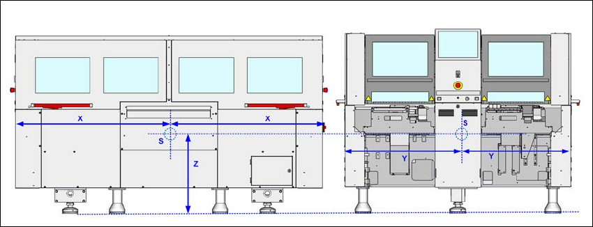
3.3.4 Placement machine center of gravity
3
Fig. 3.3 - 6 Placement machine center of gravity in millimeters
X = 100
Y = 1050mm
Z = 630 mm
S = center of gravity
These center of gravity coordinates relate to placement machines with a PCB conveyor height of
930 mm.
3 Technical data and assemblies Instruction manual SIPLACE CA4 V2
3.4 Overview of the modules From software version 713.0 Edition 12/2019
110
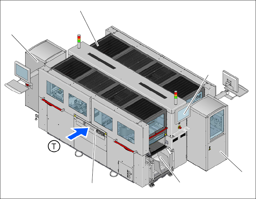
3.4 Overview of the modules
3
3
Fig. 3.4 - 1 Overview of the modules
(1) Location 1 with component trolley, tape cutter, empty tape duct and gantry with placement
head
(2) Location 2 with SIPLACE Wafer System (SWS) and gantry with placement head
(3) Location 3 with component trolley, tape cutter, empty tape duct and gantry with placement
head
(4) Location 2 with SIPLACE Wafer System (SWS) and gantry with placement head
(5) Monitor with keyboard (2x)
(6) Board conveyor
(T) Direction of PCB conveyor
(1)
(2)
(3)
(4)
(5)
(6)

Instruction manual SIPLACE CA4 V2 3 Technical data and assemblies
From software version 713.0 Edition 12/2019 3.5 Placement head
111
3.5 Placement head
3.5.1 SIPLACE SpeedStar C&P20 M2 for high-precision placement
The SIPLACE SpeedStar C&P20 M is available for top precision placement in the
SIPLACE CA4 V2.
3
CAUTION
Always take hold of the handle to push the placement head
The placement head may only be moved by pushing manually against the handle provid-
ed.