00198505-01_SM_SIPLACE_SmartFeeder_EN.pdf - 第111页
7 Repairs to SmartFeeder 8 mm X 7.10 Tamp wheel Service Manual SIPLACE SmartFeeder 4 - 104 mm X 11/2017 111 ► Press the rocker into the spring (4) . ► Move the rocker until you can completely see the drilled hole for the…
7 Repairs to SmartFeeder 8 mm X
7.9 Rocker
110 Service Manual SIPLACE SmartFeeder 4 - 104 mm X 11/2017
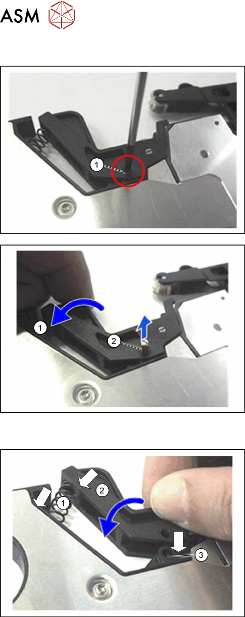
7.9.1 Removing the rocker assembly
► Carefully place the feeder module with the right
side down on a stable, level and clean surface.
► Use a size 1 slotted screwdriver to loosen the
bearing shaft (1) belonging to the rocker.
► Gently press the rocker backwards, against the
spring tension.
► Pull the bearing shaft completely out of the
rocker.
► Relax the spring, by letting the rocker slowly rise
up again.
► Lift the rocker up and out of the feeder module.
► Remove the spring (2).
7.9.2 Fitting the rocker assembly
► Carefully place the feeder module with the right
side down on a stable, level and clean surface.
► Insert the spring(1) into the base of the feeder
module.
► Fit the rocker(2) onto the spring.
► Press the rocker over the rocker holder(3).
7 Repairs to SmartFeeder 8 mm X
7.10 Tamp wheel
Service Manual SIPLACE SmartFeeder 4 - 104 mm X 11/2017 111
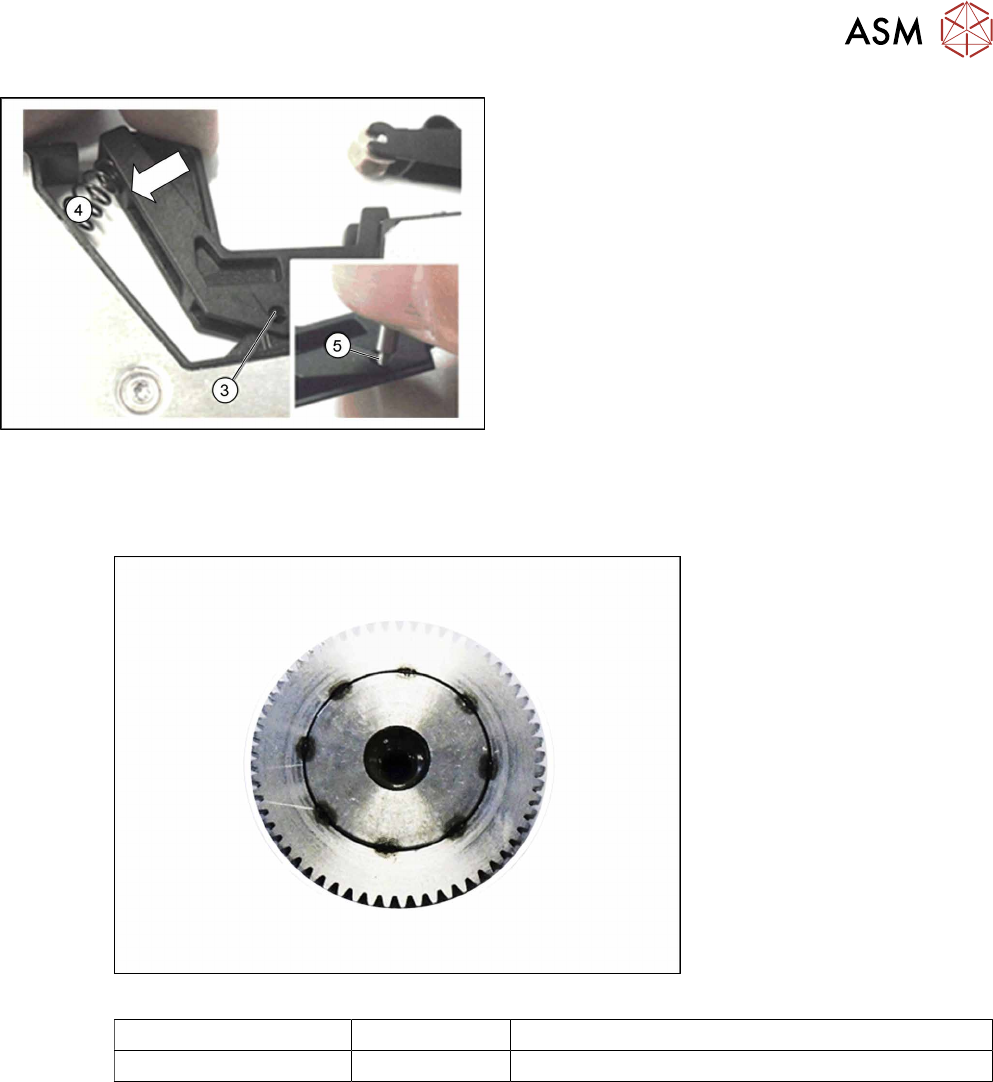
► Press the rocker into the spring (4).
► Move the rocker until you can completely see the
drilled hole for the rocker holder through the
drilled hole for the rocker itself(3).
► Push the bearing shaft(5) into the drilled hole,
with the thread first.
► Fasten the bearing shaft hand-tight with a size 1
slotted screwdriver.
7.10 Tamp wheel
Required spare part
Fig.34: Knurled tamp wheel assy.
Feeder module Item no. Designation
SmartFeeder 8mm X 03102274-xx Knurled tamp wheel assy. X8Smart
Required tools
●
Phillips screwdriver, small
●
Flat-bladed screwdriver
●
Allen key size 4
●
Tweezers
7 Repairs to SmartFeeder 8 mm X
7.10 Tamp wheel
112 Service Manual SIPLACE SmartFeeder 4 - 104 mm X 11/2017
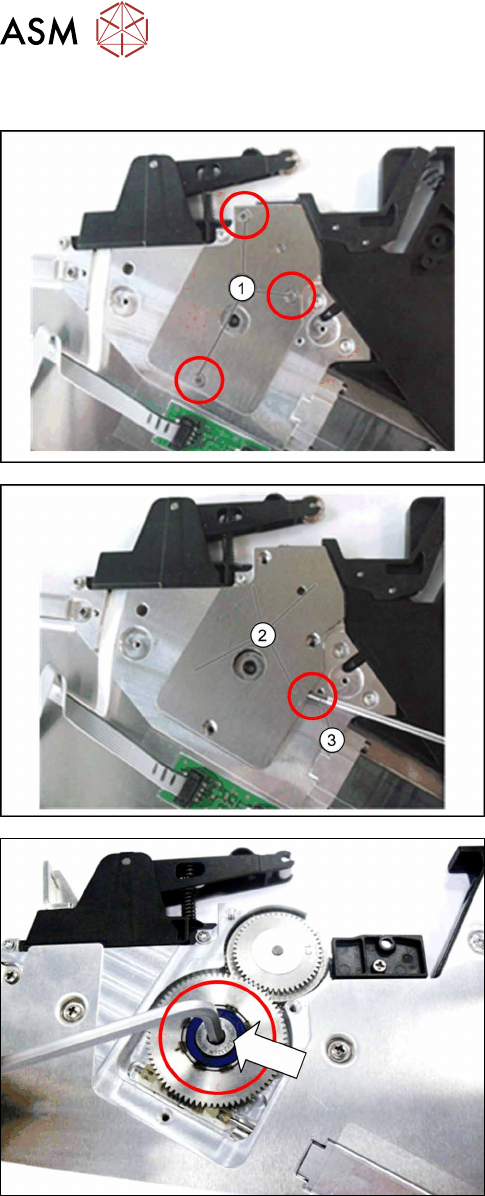
7.10.1 Removing the tamp wheel
► Carefully place the feeder module with the right
side down on a stable, level and clean surface.
► Remove the left side cover (see 7.3.1 "Removing
the Left Side Cover" [}83]).
► Remove the 3 Phillips screws(1) marked in the
diagram from the bearing cap for the foil drive.
► Lift the bearing cap(2) up with a pair of tweezers
or a small screwdriver(3) and remove it.
► Remove the rocker (see 7.9.1 "Removing the
rocker assembly " [}110]).
► Remove the wiper. (see 7.11.1 "Removing the
wiper 8 mm X " [}117])..
► Loosen the Allen bolt on the spiral gear.
Use a size 4 Allen key for this.