00198505-01_SM_SIPLACE_SmartFeeder_EN.pdf - 第193页
9 Repairs to SmartFeeder 12 mm X / 16 mm X 9.6 Splice Sensor Service Manual SIPLACE SmartFeeder 4 - 104 mm X 11/2017 193 9.6 Splice Sensor NOTICE Splice sensor or dummy The feeder module can be fitted with either a splic…
9 Repairs to SmartFeeder 12 mm X / 16 mm X
9.5 Pickup window
192 Service Manual SIPLACE SmartFeeder 4 - 104 mm X 11/2017
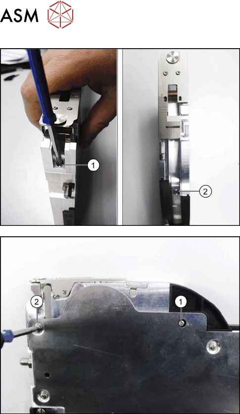
► Stand the feeder module up.
► Hold the pickup window and tape duct with one
hand (as shown) to counteract the spring force of
the compression spring.
► Fasten the front screw of the tape duct with
0.6Nm(1).
► Fasten the back screw with 0.6Nm to the tape
duct.(2)
► Carefully place the feeder module with the right
side down on a stable, level and clean surface.
► Fasten the screw with 0.6Nm to the splice
sensor.(1)
► Fasten the top left screw with 0.6Nm to the side
cover(1).
9 Repairs to SmartFeeder 12 mm X / 16 mm X
9.6 Splice Sensor
Service Manual SIPLACE SmartFeeder 4 - 104 mm X 11/2017 193
9.6 Splice Sensor
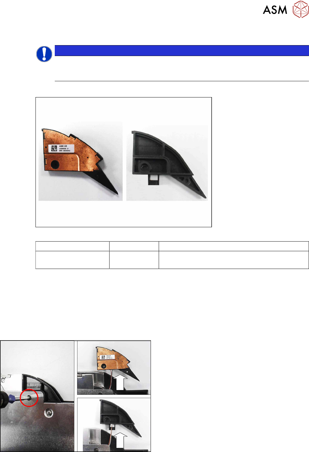
NOTICE
Splice sensor or dummy
The feeder module can be fitted with either a splice sensor or a dummy splice sensor. The
procedure is the same in both cases.
Required spare part
Fig.67: Splice sensor (left) / Splice sensor dummy (right)
Feeder module Item no. Designation
SmartFeeder 12mm X
SmartFeeder 16mm X
03085638- xx
03085517Sxx
Splice sensor X12/X16 V2
Dummy splice sensor X12/X16 V2
Required tools
●
Flat-bladed screwdriver size 1
●
Phillips screwdriver 0.6Nm
●
TORX screwdriver 0.6Nm, size T8
●
Tweezers
9.6.1 Removing the Splice Sensor (Dummy)
► Carefully place the feeder module with the right-
side side down on a stable, level and clean sur-
face.
► Remove the screw shown in the diagram.
► Remove the splice sensor or splice sensor
dummy and carefully pull out the cable a little.
9 Repairs to SmartFeeder 12 mm X / 16 mm X
9.6 Splice Sensor
194 Service Manual SIPLACE SmartFeeder 4 - 104 mm X 11/2017
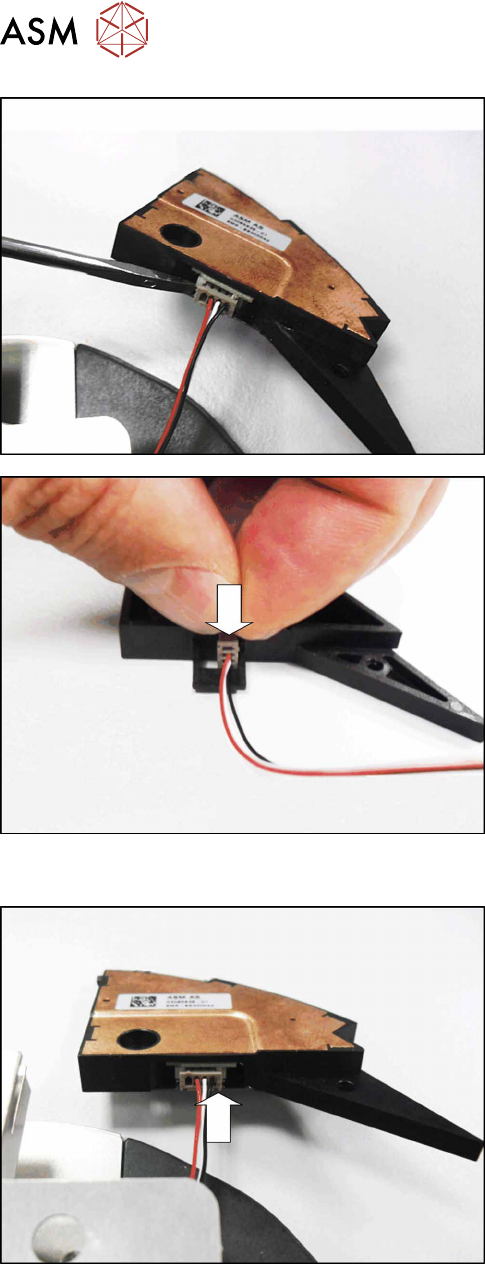
For the splice sensor:
► Carefully lever the connector of the splice sensor
cable out of the connection. Use a small screw-
driver or pair of tweezers to help you.
For the splice sensor dummy:
► Pull the splice sensor cable out of the splice
sensor dummy.
9.6.2 Fitting the Splice Sensor Dummy
For the splice sensor:
► Fit the 4-pin connector for the splice sensor cable
onto the splice sensor, as shown in the diagram.