00198505-01_SM_SIPLACE_SmartFeeder_EN.pdf - 第242页
10 Repairs to SmartFeeder 24 - 104 mm X 10.6 Splice sensor 242 Service Manual SIPLACE SmartFeeder 4 - 104 mm X 11/2017 10.6.1 Removing the splice sensor (dummy) The splice sensor (dummy) is located behind the pickup wind…
10 Repairs to SmartFeeder 24 - 104 mm X
10.6 Splice sensor
Service Manual SIPLACE SmartFeeder 4 - 104 mm X 11/2017 241
10.5.3 Replacing the Öffner pickup window
The opener for the pickup window is fitted with a M2.5
x 5mm Phillips screw and washer to the base unit.(1)
The screw is for loosening and fastening and can be
accessed via a hole on the left side of the tape
duct.(2)
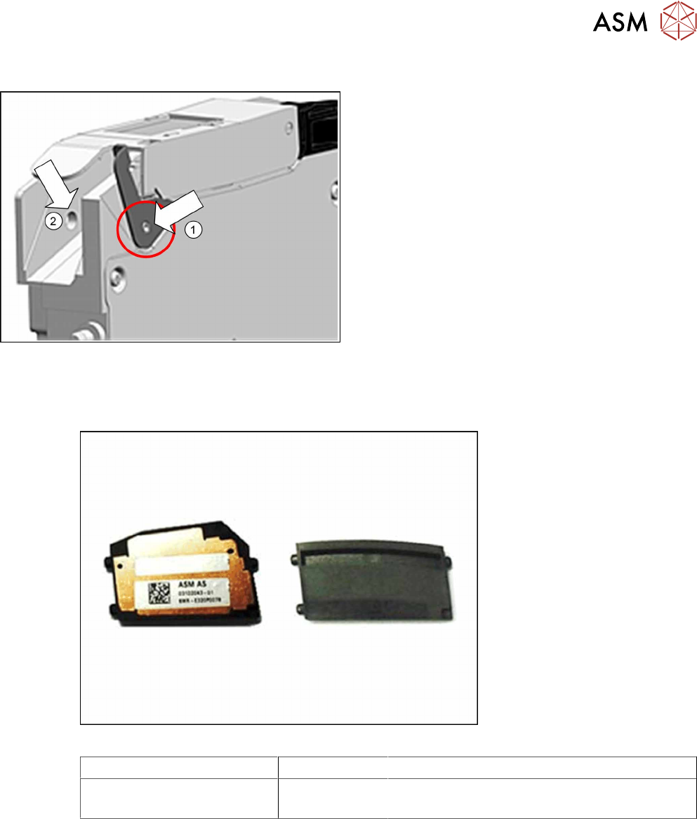
10.6 Splice sensor
Required spare part
Fig.87: Splice sensor (left) / dummy splice sensor (right)
Feeder module Item no. Designation
SmartFeeder 24 - 104mmX 03107028 -xx
03104558 -xx
Splice sensor X8Smart assembly
Dummy splice sensor X8Smart
Required tools
●
TORX screwdriver 0.6Nm, size T8
10 Repairs to SmartFeeder 24 - 104 mm X
10.6 Splice sensor
242 Service Manual SIPLACE SmartFeeder 4 - 104 mm X 11/2017
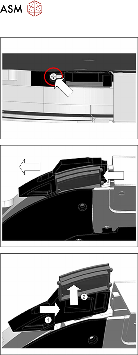
10.6.1 Removing the splice sensor (dummy)
The splice sensor (dummy) is located behind the
pickup window and is held by the "filler piece splice
sensor".
► Place the feeder module in a stable, upright posi-
tion.
► Loosen the Phillips screw shown in the diagram,
until the filler piece can be moved.
► Carefully push the filler piece in the direction of
the arrow, as far as the stop.
► Push the splice sensor (-dummy) to the right and
out of the filler piece.(1)
► Lift the splice sensor (-dummy) up and out.(2)
10 Repairs to SmartFeeder 24 - 104 mm X
10.6 Splice sensor
Service Manual SIPLACE SmartFeeder 4 - 104 mm X 11/2017 243
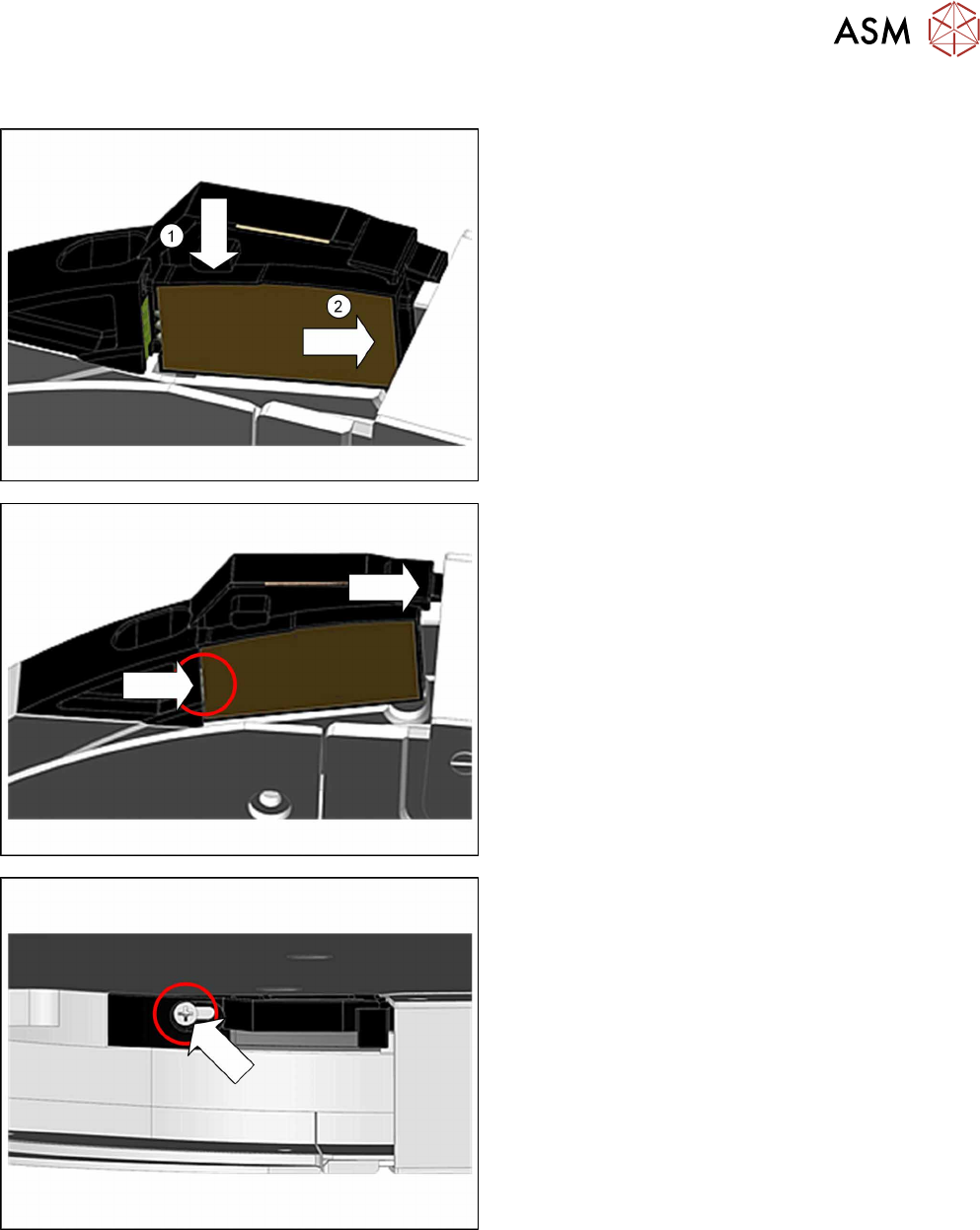
10.6.2 Fitting the splice sensor dummy
► Place the feeder module in a stable, upright posi-
tion.
► Lift the splice sensor (dummy) as shown into the
filler piece.(1)
Make sure that the 2 fixing pins point to the front
and the 3 contact pins to the back.
► Push the splice sensor (dummy) with the fixing
pins first as far as the stop, in the direction of the
arrow: to the right.(2)
► Push the filler piece as far as the stop to the right
(direction of the arrow).
When fitting the splice sensor, make sure that the
contact pins of the sensor touch the contacts on
the filler piece.
► Fix the splice sensor (dummy) with the marked
screw. Use a Phillips screwdriver with 0.6 Nm for
this.