00198505-01_SM_SIPLACE_SmartFeeder_EN.pdf - 第280页
10 Repairs to SmartFeeder 24 - 104 mm X 10.13 Handle assembly with control panel 280 Service Manual SIPLACE SmartFeeder 4 - 104 mm X 11/2017 ► Carefully place the feeder module with the left side down on a stable, level …
10 Repairs to SmartFeeder 24 - 104 mm X
10.13 Handle assembly with control panel
Service Manual SIPLACE SmartFeeder 4 - 104 mm X 11/2017 279
10.13 Handle assembly with control panel
Required spare part
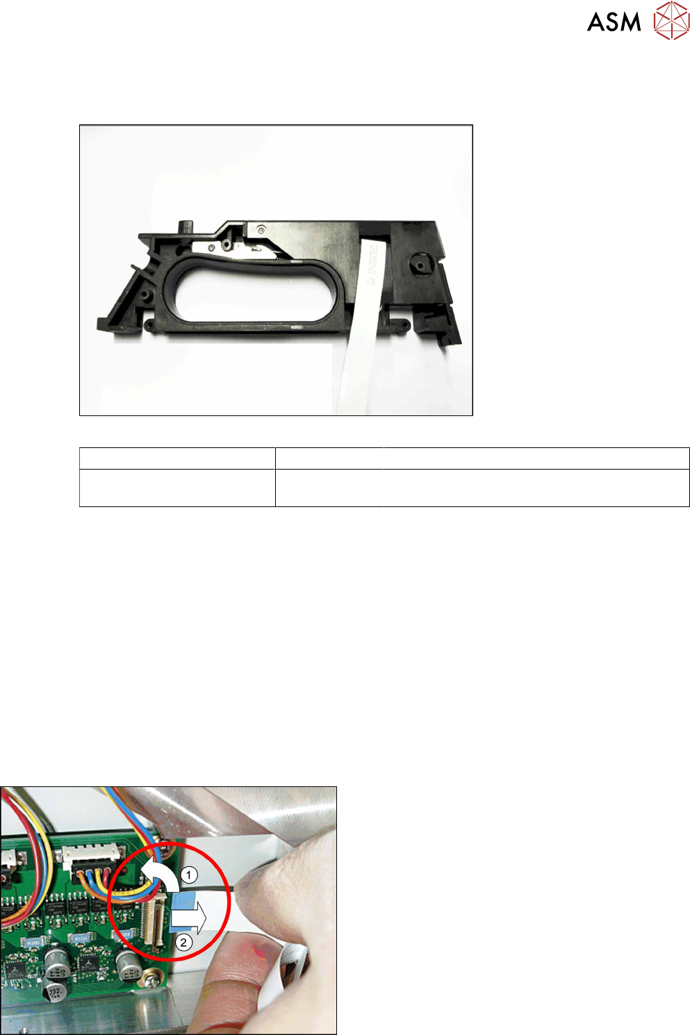
Fig.102: Handle X24-104 assy.
Feeder module Item no. Designation
SmartFeeder 24 – 104 mm X 03112666Sxx Handle assembly X24-104.
(prefitted with flat ribbon cable)
Required tools
●
Phillips screwdriver 0.6Nm
●
TORX screwdriver size T8, 0.6Nm
●
Tweezers
10.13.1 Removing the handle assembly
► Carefully place the feeder module with the left side down on a stable, level and clean surface.
► Remove the right side wall (see 10.3.3 "Rear side wall on the right" [}231])
► Remove the pressure spring from the rocker (see 10.9.2.1 "Replacing the pressure spring and
spring support" [}271]).
► Carefully place the feeder module with the right side down on a stable, level and clean sur-
face.
► Remove the left side plate (see 10.3.1 "Removing/fitting the left side plate" [}230]).
► Open the bar on the flat ribbon connection on the
control board.(1)
► Unplug the flat ribbon cable form the connec-
tion.(2)
10 Repairs to SmartFeeder 24 - 104 mm X
10.13 Handle assembly with control panel
280 Service Manual SIPLACE SmartFeeder 4 - 104 mm X 11/2017
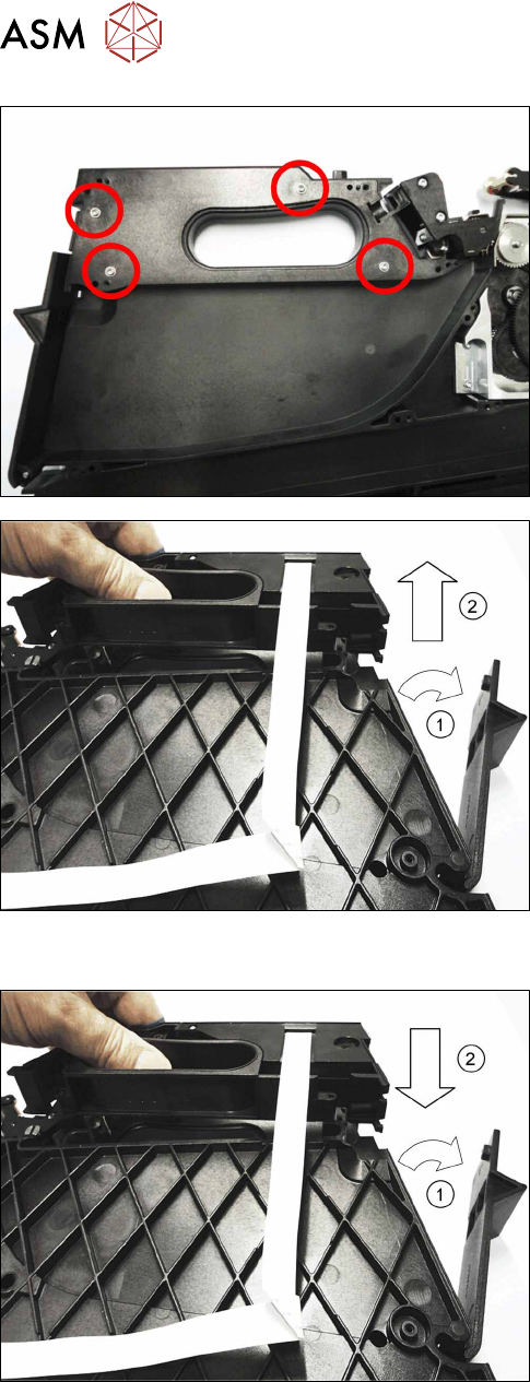
► Carefully place the feeder module with the left
side down on a stable, level and clean surface.
► Remove the four screws marked in the diagram,
which are fastening the handle. Use a size T8
TORX screwdriver for this.
► Carefully place the feeder module with the right
side down on a stable, level and clean surface.
► Open the tape container flap.(1)
► Lift the handle straight up and out of the feeder
module base unit. (2)
10.13.2 Fitting the handle assembly
► Carefully place the feeder module with the right
side down on a stable, level and clean surface.
► Open the flap on the foil container.(1)
► Insert the handle straight down and into the
feeder module base unit. (2)
► Close the flap on the foil container.
10 Repairs to SmartFeeder 24 - 104 mm X
10.13 Handle assembly with control panel
Service Manual SIPLACE SmartFeeder 4 - 104 mm X 11/2017 281
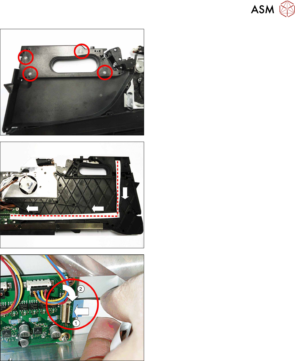
► Carefully place the feeder module with the left
side down on a stable, level and clean surface.
► Fasten the handle using the four marked (see
diagram) screws. Use a TORX screwdriver and
0.6 Nm for this.
► Carefully place the feeder module with the right
side down on a stable, level and clean surface.
► Run the cable as shown.
When running the cable, make sure that the blue
side points upwards at the end of the cable..
► Insert the end of the flat ribbon cable (with the
blue side pointing upwards) up to the stop in the
flat ribbon connection shown on the control
board.(1)
► Close the connection and make sure that the
cable it firmly fitted.(2)
► Fix the left side plate into place. (see 10.3.1 "Removing/fitting the left side plate" [}230]).
► Carefully place the feeder module with the right side down on a stable, level and clean sur-
face.
► Insert the pressure spring into the rocker (see 10.9.2.1 "Replacing the pressure spring and
spring support" [}271]).
► Fasten the right rear side wall (see 10.3.3 "Rear side wall on the right" [}231])