00198505-01_SM_SIPLACE_SmartFeeder_EN.pdf - 第30页
6 Repairs to SmartFeeder 4 mm X 6.3 Side Covers 30 Service Manual SIPLACE SmartFeeder 4 - 104 mm X 11/2017 6.3 Side Covers NOTICE Avoiding damaging the board To avoid damaging the threaded bolts on the printed circuit bo…
6 Repairs to SmartFeeder 4 mm X
6.2 Rear Sliding Guide
Service Manual SIPLACE SmartFeeder 4 - 104 mm X 11/2017 29
6.2.1 Removing the Sliding Guide
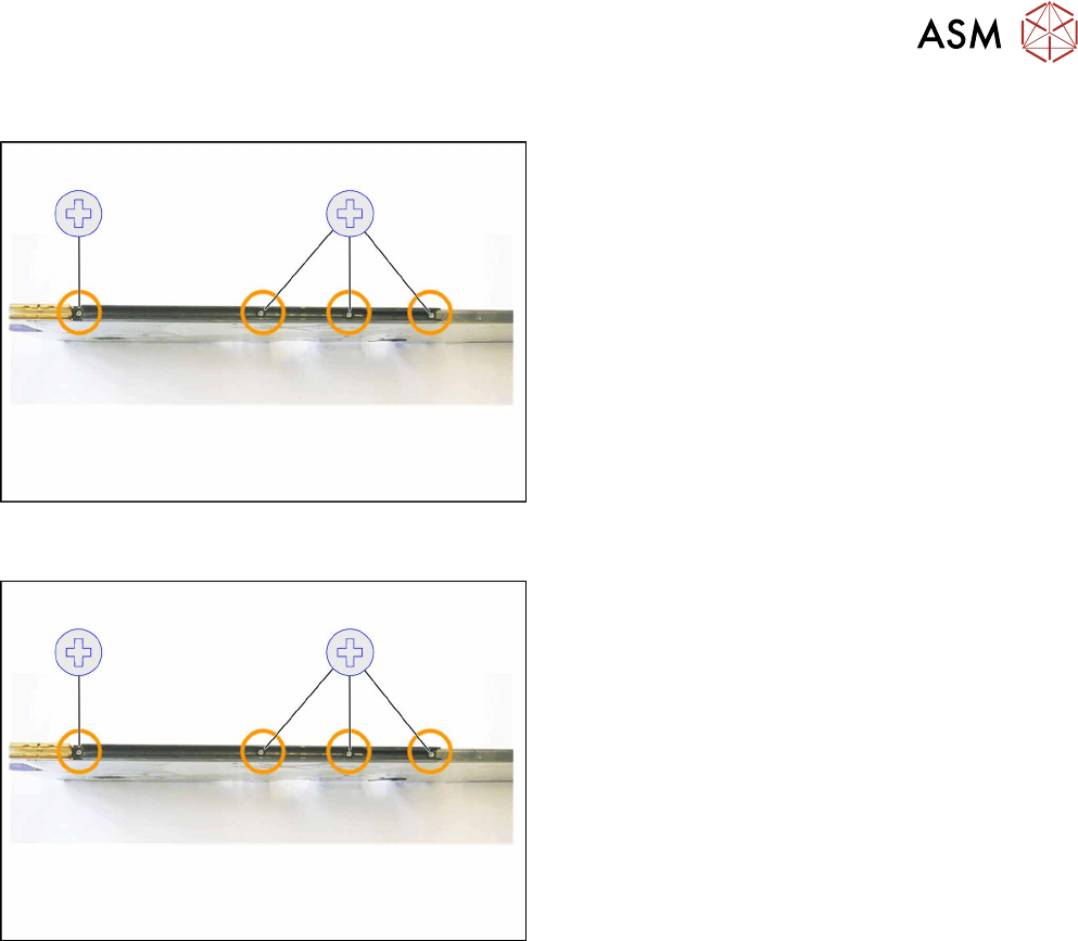
► Turn the feeder module so that its underside is at
the top.
► Remove the left Phillips screw.
► Remove the other three Phillips screws.
► Lift the gliding slide upwards and off.
6.2.2 Fitting the Sliding Guide
► Turn the feeder module so that its underside is at
the top.
► Fit the guiding slide – as illustrated – to the un-
derside of the feeder module.
Observe the arrangement of the drilled holes in
the guiding slide.
► Push the guiding slide, as shown, to the left
(front) towards the front guiding slide, as far as
the stop.
► Now lower the two snap tabs of the guiding slide
into the openings provided on the underside of
the feeder module.
► Fasten the sliding guide on the left side to the
feeder module, using the Phillips screw "ISO
7045 - M2.5 x 6-A2-50-H" tightened to 0.6N.
► Fasten the sliding guide with the other 3 screws,
tightened to 0.6Nm, to the feeder module.
Phillips screws are fitted here on the Smart-
Feeder 4mmX.
6 Repairs to SmartFeeder 4 mm X
6.3 Side Covers
30 Service Manual SIPLACE SmartFeeder 4 - 104 mm X 11/2017
6.3 Side Covers
NOTICE
Avoiding damaging the board
To avoid damaging the threaded bolts on the printed circuit board, only remove the side
cover if the other side cover has been fully fitted i.e. with all screws.
Required spare part
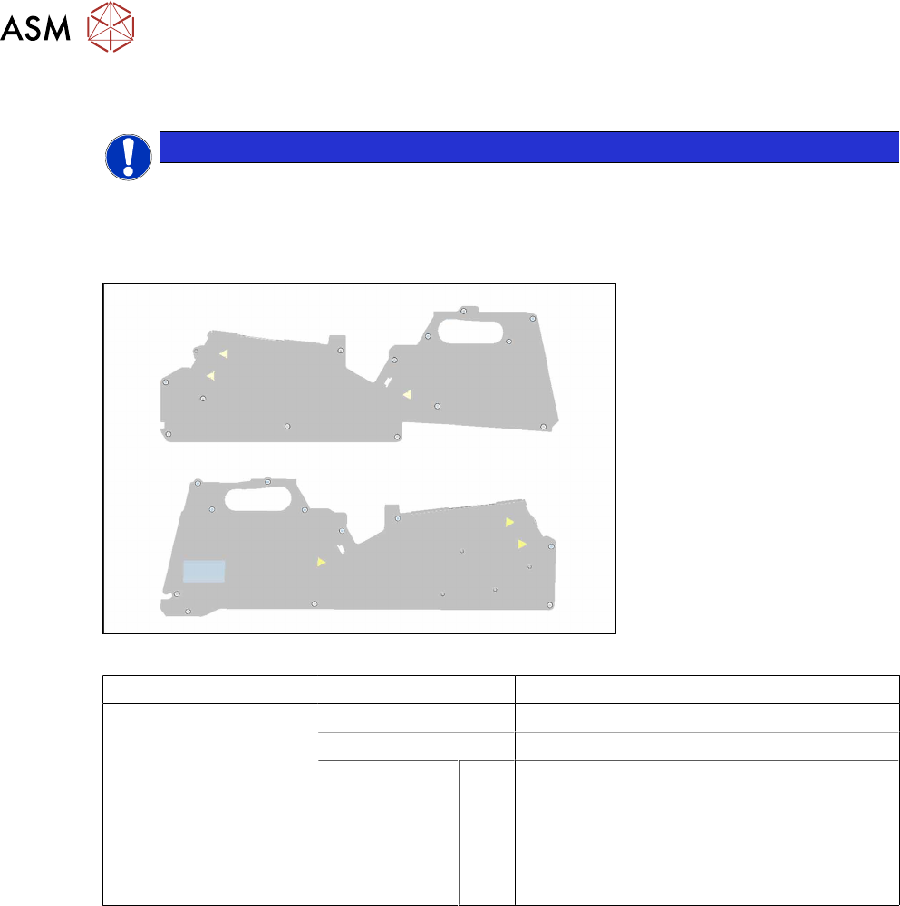
Fig.4: Side plate left assy. X8Smart (top), side plate right assy. X8Smart (bottom)
Feeder module Item no. Designation
SmartFeeder 4mmX 03100525Sxx Side plate left assy. X8Smart
03100526Sxx Side plate right assy. X8Smart
03033796-xx
03071822-xx
03023227-xx
03071821-xx
03044543-xx
A
B
C
D
E
Screws:
RF-SN75 2.5 x 6-9.8 (14x)
SN 213307-H-M2.5 x 5-A2-70 (8x)
ISO 7046-2-M2.5 x 5-A2-70-H (4x)
SN 213307-H-M2.5 x 3-A2-70 (2x)
RF-SN85-2.5 x 7.5-9.8 (1x)
Required tools
●
Phillips screwdriver 0.9Nm
●
TORX screwdriver 0.6Nm, size T8
6 Repairs to SmartFeeder 4 mm X
6.3 Side Covers
Service Manual SIPLACE SmartFeeder 4 - 104 mm X 11/2017 31
6.3.1 Removing the Left Side Cover
NOTICE
Avoiding damaging the board
Before you remove the left side cover, make sure that the right side cover has been com-
pletely fixed in place with all screws. If not, the threaded bolts could be damaged on the
board.
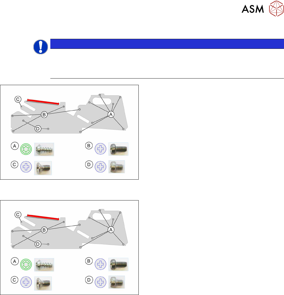
► Carefully place the feeder module with the right
side down on a stable, level and clean surface.
► Loosen the screws as shown in the diagram.
You need a TORX screwdriver for the screws marked
A.
You need a Phillips screwdriver for the screws marked
B, Cand D.
The side cover is only inserted in the upper part of the
frame in the area marked red.
► Pull the side cover down and out.
6.3.2 Fitting the Left Side Cover
► Carefully place the feeder module with the right
side down on a stable, level and clean surface.
► Push the side cover (area marked in red) under
the rail as shown, as far as the stop.
► Fix the screws as shown in the diagram. Begin
with the inner screws and work towards the out-
side.
You need a Phillips screwdriver with 0.9 Nm for the
screws marked B, Cand D.
You need a TORX screwdriver with 0.6 Nm for the
screws marked A.