00198505-01_SM_SIPLACE_SmartFeeder_EN.pdf - 第214页
9 Repairs to SmartFeeder 12 mm X / 16 mm X 9.8 Foil rocker 214 Service Manual SIPLACE SmartFeeder 4 - 104 mm X 11/2017 9.8.3 Cable photo interrupter Required spare part Fig.76: Cable light barrier transmitter Feeder mod…
9 Repairs to SmartFeeder 12 mm X / 16 mm X
9.8 Foil rocker
Service Manual SIPLACE SmartFeeder 4 - 104 mm X 11/2017 213
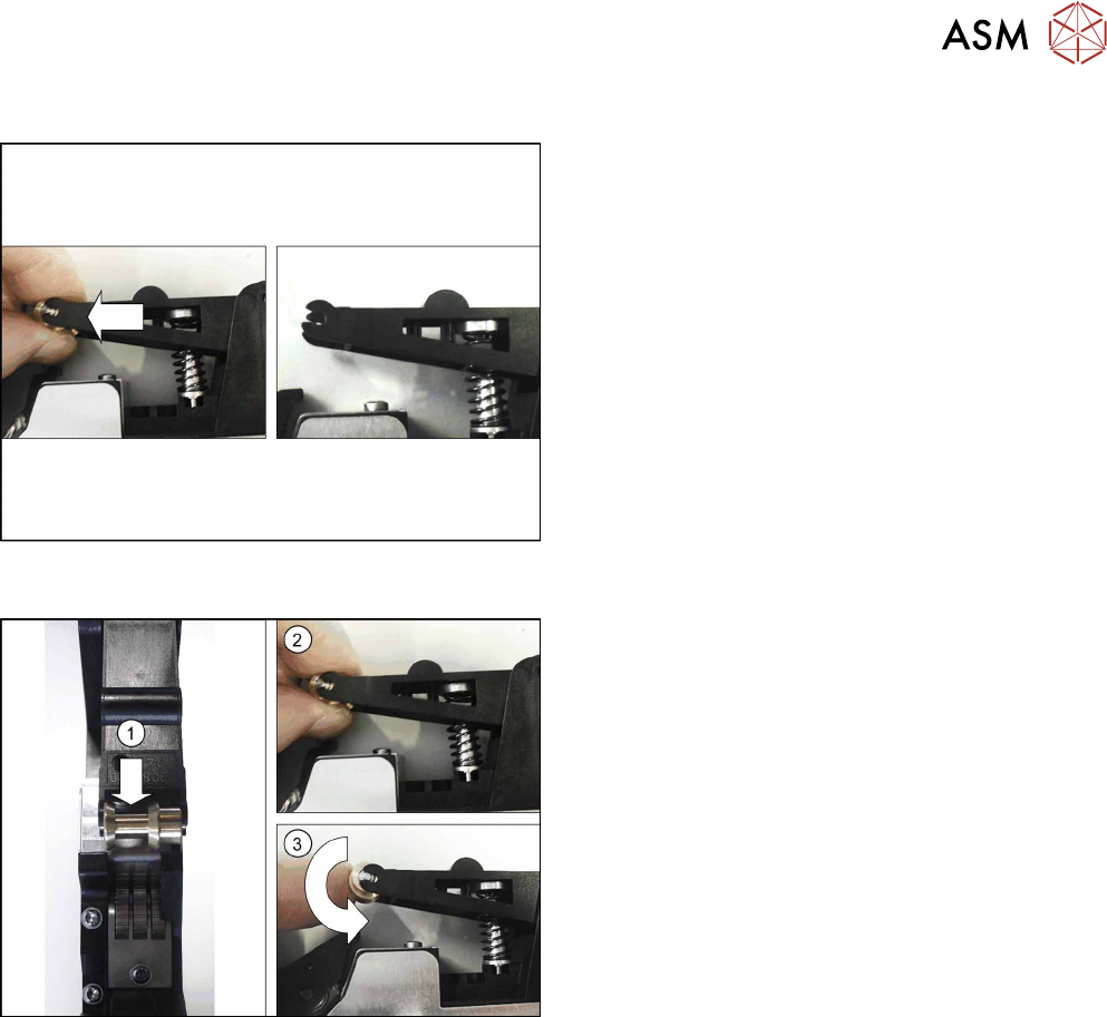
9.8.2.1 Removing the Roller/Roller Axle
► Carefully place the feeder module on its right
side.
► Pull the roller out of the rocker, together with the
roller axle.
Make sure that the roller axle is not lost.
9.8.2.2 Fitting the Roller/Roller Axle
Note:
When using a SmartFeeder 12mmX, make sure that
the roller is fitted in the correct position. The foil
guide(1) must be on the left side.
► Push the roller axle into the roller.
► Press both ends of the roller axle.(2)
► Make sure that the roller be easily moved.(3)
9 Repairs to SmartFeeder 12 mm X / 16 mm X
9.8 Foil rocker
214 Service Manual SIPLACE SmartFeeder 4 - 104 mm X 11/2017
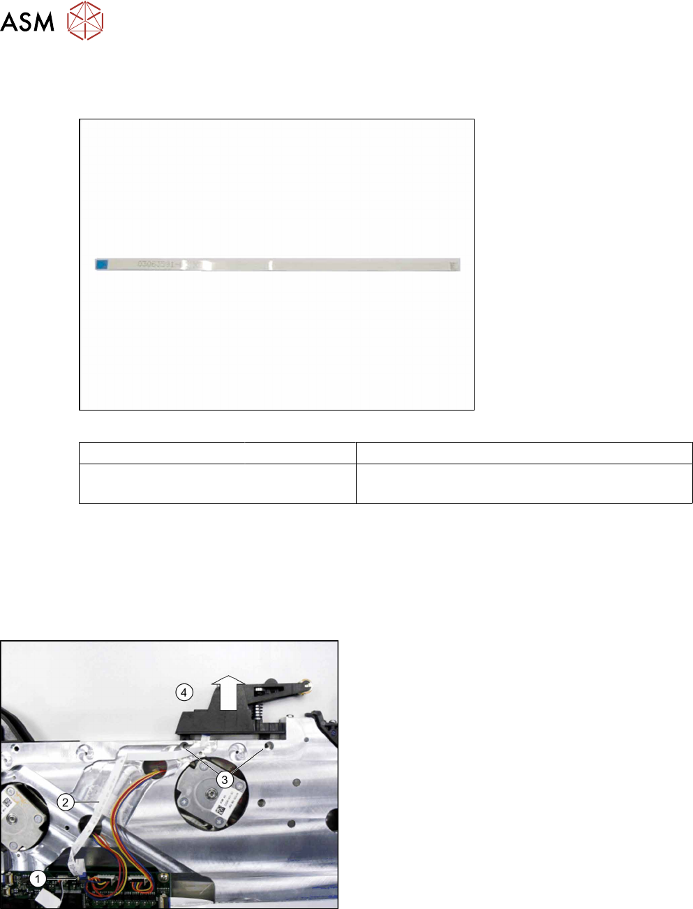
9.8.3 Cable photo interrupter
Required spare part
Fig.76: Cable light barrier transmitter
Feeder module Item no. Designation
SmartFeeder 12mm X
SmartFeeder 16mm X
03063591- xx Cable for light barrier transmitter X2x8
Required tools
●
Phillips screwdriver 0.6Nm
●
TORX screwdriver 0.6Nm, size T8
●
Double-sided adhesive tape
9.8.3.1 Removing the Photo Interrupter Cable
► Remove the left side cover (see 9.3.1 "Removing
the Left Side Cover" [}184].
► Swing the holder on the flat ribbon connection of
the control board up and remove the cable (1).
► Pull the flat ribbon cable off the double-sided ad-
hesive tape at the marked point (2).
► Use a T8 TORX screwdriver to remove the two
screws(3), fastening the foil rocker.
► Make sure that the two spring disks DIN 127-
B2.5-A2 are not lost.
► Pull the foil rocker up and off(4).
9 Repairs to SmartFeeder 12 mm X / 16 mm X
9.8 Foil rocker
Service Manual SIPLACE SmartFeeder 4 - 104 mm X 11/2017 215
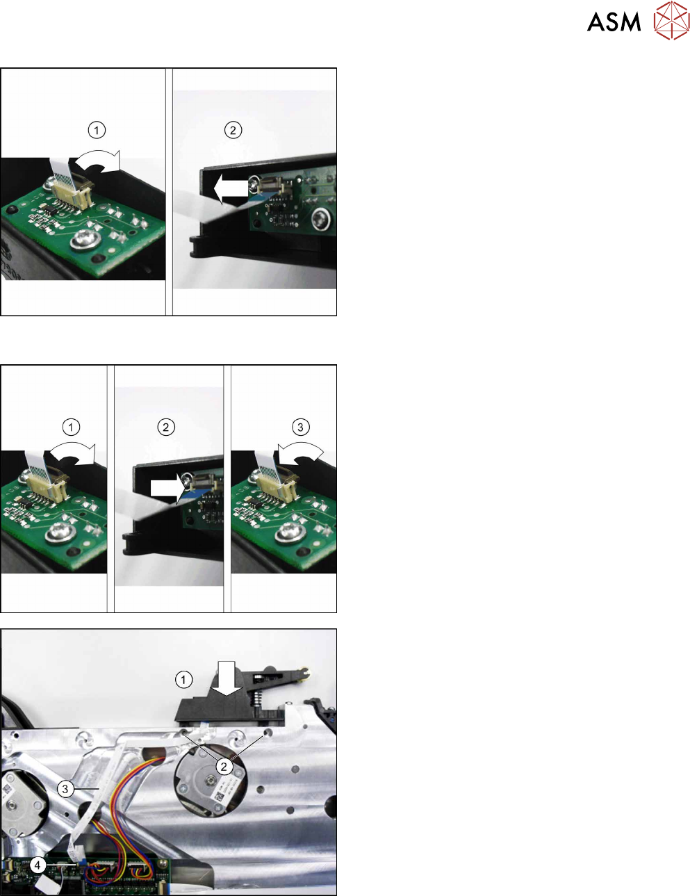
► Turn the foil rocker into the position shown in the
diagram.
► Swing the holder on the flat ribbon connection
up(1) and pull out the cable(2).
9.8.3.2 Fitting the Photo Interrupter Cable
► Turn the foil rocker into the position shown in the
diagram.
► Swing the holder on the flat ribbon connection
up(1).
► Push the cable (with the blue side pointing up-
wards) up to the stop into the flat ribbon connec-
tion(2).
Make sure that the cable contacts lie against the
contacts on the connection.
► Swing the holder on the flat ribbon connection
down(3).
► Fit the foil rocker from above into the position
shown on the feeder module(1).
► Fit one washer in each foil rocker and fasten the
foil rockers with the two screws(2). Use a size T8
TORX screwdriver with 0.6 Nm. for this.
► Run the cable in the duct as shown in the dia-
gram.
► Push the flat ribbon cable onto the double-sided
adhesive tape at the marked point (3).
Replace the adhesive tape if necessary.
► Push the cable (with the blue side pointing up-
wards) up to the stop, into the flat ribbon connec-
tion on the control board (4).
Make sure that the cable contacts lie against the
contacts on the connection.
► Swing the holder on the flat ribbon connection
down(4).
► Fasten the left side cover (see 9.3.2 "Fitting the
Left Side Cover" [}184]).