00198505-01_SM_SIPLACE_SmartFeeder_EN.pdf - 第96页
7 Repairs to SmartFeeder 8 mm X 7.6 Splice sensor 96 Service Manual SIPLACE SmartFeeder 4 - 104 mm X 11/2017 7.6.2 Performing a function test Prerequisite: to test the splice sensor, you need a test tape i.e. a piece of …
7 Repairs to SmartFeeder 8 mm X
7.6 Splice sensor
Service Manual SIPLACE SmartFeeder 4 - 104 mm X 11/2017 95
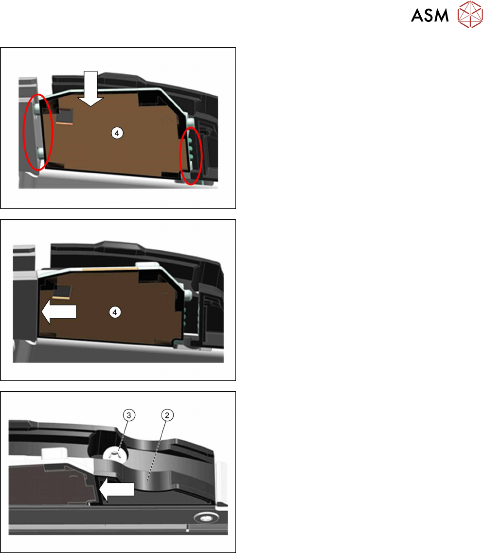
► Insert the splice sensor(4) in place of the
dummy, as shown.
Make sure that the 2 fixture pins point forwards
and the 3 contact pins point backwards.
► Push the splice sensor(4) forwards, in the direc-
tion of the arrow, as far as the stop.
► Push the filling piece(2) in the direction of the ar-
row, towards the splice sensor, as far as the stop.
► Fix the filling piece with the TORX screw(3) and
0.6Nm.
The splice sensor is automatically contacted by the
board on the filling piece and is then recognized by the
software.
7 Repairs to SmartFeeder 8 mm X
7.6 Splice sensor
96 Service Manual SIPLACE SmartFeeder 4 - 104 mm X 11/2017
7.6.2 Performing a function test
Prerequisite: to test the splice sensor, you need a test tape i.e. a piece of tape with a splice rivet
pressed onto it.
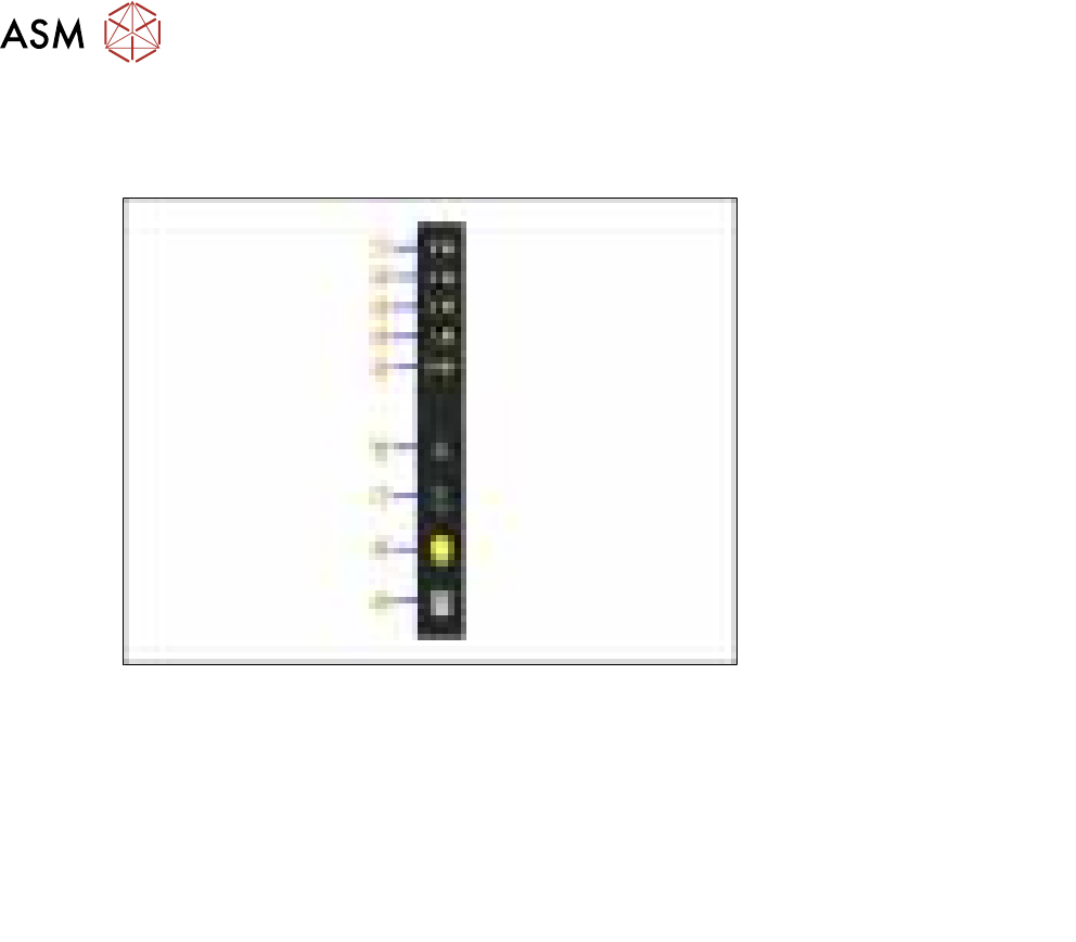
Fig.28: Control panel
1. LED 8 – 8mm pitch
(active only on SmartFeeder 8mmX)
6. FORWARDS button
2. LED 4 – 4mm pitch 7. BACKWARDS button
3. LED 2 – 2mm pitch 8. FOIL button
4. LED 1 – 1mm pitch 9. SET button
5. LED M – menu
Shines when an operator menu is active
► Place the feeder module on a single slot EDIF or on a changeover table for X feeders which is
connected to a placement machine.
► Press and hold the gray SET button on the operating panel(9) until the function test is en-
abled.
► Press the yellow foil button four times briefly(8).
After the first press of the FOIL button, the LEDM will switch on.
After the second press, LED1 will also be switched on.
After the third press, LED2 will also be switched on.
After the fourth press, LED 4 will also be switched on.
The menu for the splice sensor function test has now been selected.
► Release the gray SET button, the function test has now been enabled.
► Move the test tape with the splice rivet pressed onto it up to the sensor.
If the splice sensor recognizes the splice rivet, LED 8 will shine.
If LED 8 stays off, this means that the splice rivet was not recognized. Check whether the splice
sensor was fitted properly.
If the sensor is then not recognized, check whether the flat ribbon cable for the splice sensor has
been correctly fastened (see section 7.15.2 "Fitting the control board" [}130]).
If the sensor is still not recognized, this indicates that it is probably defective and needs replacing.
► To end the test mode, press any button on the control panel. The test mode will also be ended
automatically after 1 minute.
After ending the test mode, the control panel will show the pitch currently set.
7 Repairs to SmartFeeder 8 mm X
7.7 Drives
Service Manual SIPLACE SmartFeeder 4 - 104 mm X 11/2017 97
7.7 Drives
7.7.1 Foil motor
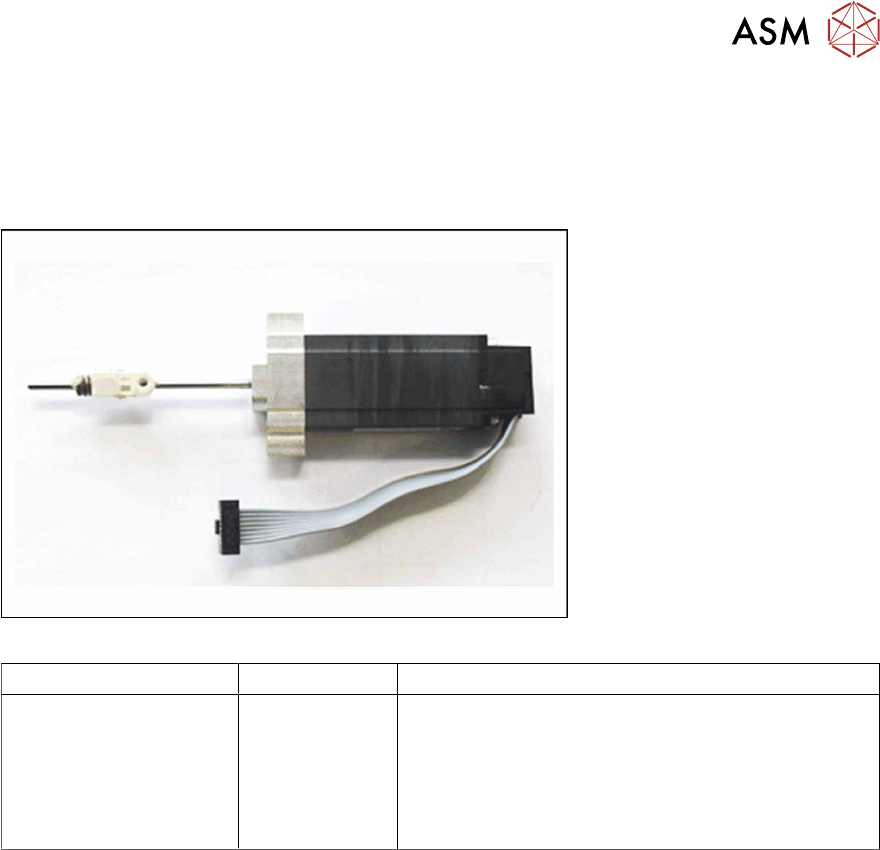
Required spare part
Fig.29: Motor coupling/foil disposal X-Series
Feeder module Item no. Designation
SmartFeeder 8mm X 03050686Sxx
03028610-xx
03012488-xx
03042536-01
Motor coupling/foil disposal X-Series
Bearing block, ceramic
SN 213307-H-M2 x 2.5-A2
(for fitting the bearing block)
ISO 4762 - M 2.5 x 12-A2-70
(for fitting the motor)
Required tools
●
Phillips screwdriver 0.9Nm
●
Flat-bladed screwdriver size 3
●
TORX screwdriver 0.6Nm, size T8
●
Angled Allen key, size 2
●
Allen key 0.9 Nm, size 4
●
Tweezers
Required consumables
●
Grease Klübersynth GE 14-151