00198505-01_SM_SIPLACE_SmartFeeder_EN.pdf - 第225页
9 Repairs to SmartFeeder 12 mm X / 16 mm X 9.13 Handle Assembly with Operating Panel Service Manual SIPLACE SmartFeeder 4 - 104 mm X 11/2017 225 ► Remove the two marked screws fastening the handle. ► Stand the feeder mod…
9 Repairs to SmartFeeder 12 mm X / 16 mm X
9.13 Handle Assembly with Operating Panel
224 Service Manual SIPLACE SmartFeeder 4 - 104 mm X 11/2017
9.13 Handle Assembly with Operating Panel
Required spare part
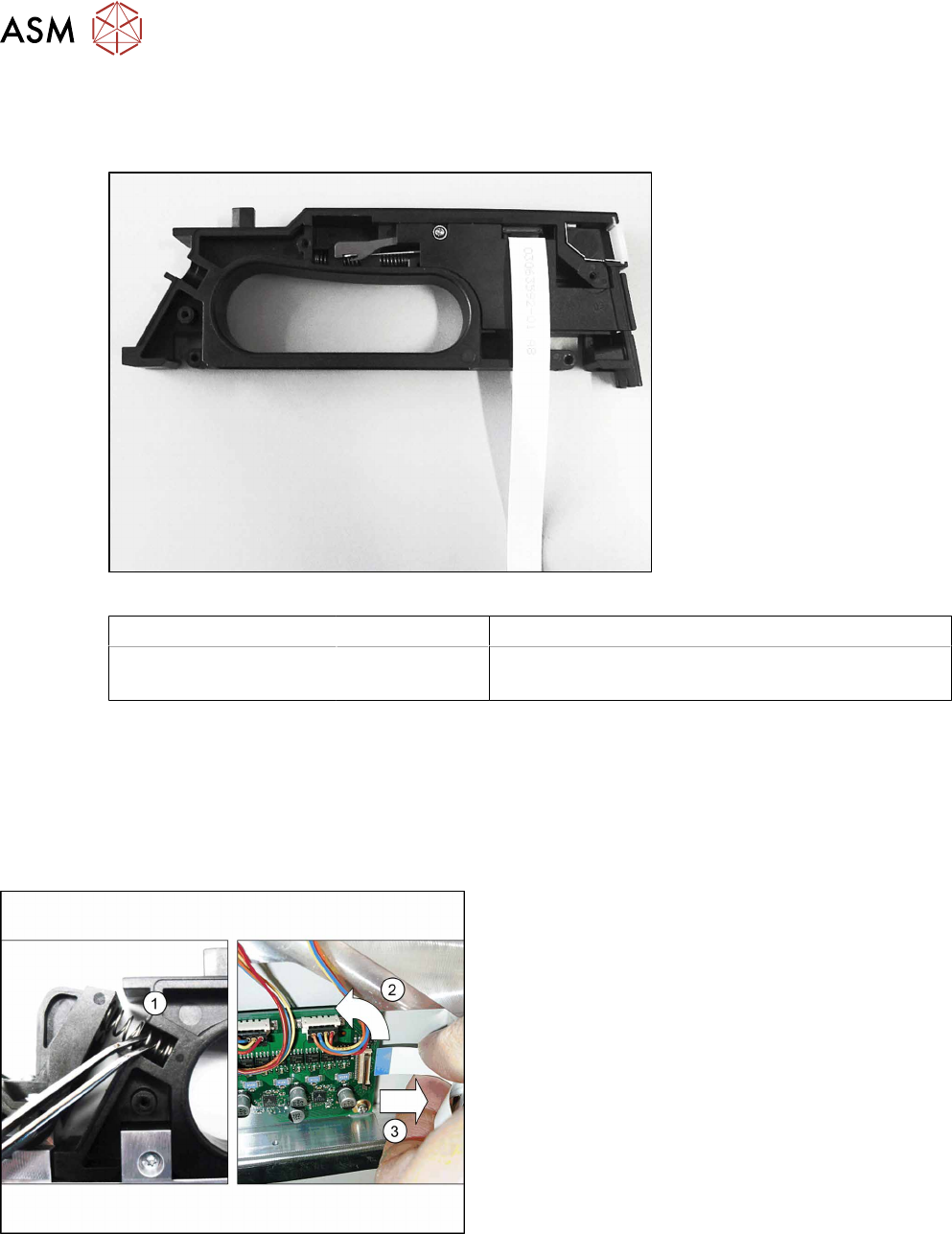
Fig.82: Handle assembly
Feeder module Item no. Designation
SmartFeeder 12mm X
SmartFeeder 16mm X
03082057Sxx Handle assembly X12/X16 V2
(prefitted with flat ribbon cable)
Required tools
●
Phillips screwdriver 0.6Nm
●
TORX screwdriver size T8, 0.6Nm
●
Tweezers
9.13.1 Removing the Handle
► Remove the left and right side cover (see 9.3.1
"Removing the Left Side Cover" [}184] and 9.3.3
"Removing the Right Side Cover" [}184]).
► Remove the two compression springs from the
rocker.(1)
► Carefully place the feeder module on its right
side.
► Open the bar on the flat ribbon connection on the
control board.(2)
► Unplug the flat ribbon cable form the connec-
tion.(3)
9 Repairs to SmartFeeder 12 mm X / 16 mm X
9.13 Handle Assembly with Operating Panel
Service Manual SIPLACE SmartFeeder 4 - 104 mm X 11/2017 225
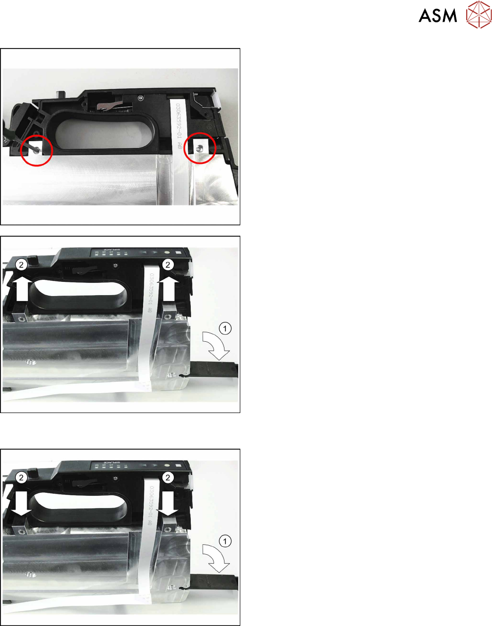
► Remove the two marked screws fastening the
handle.
► Stand the feeder module up.
► Open the foil disposal flap. (1)
► Push the handle in the direction of the arrow, up
to the right-hand side and out of the feeder mod-
ule frame. (2)
► Close the foil container flap.
► Carefully pull the flat ribbon cable off the adhes-
ive points.
9.13.2 Fitting the Handle
► Stand the feeder module up.
► Open the foil disposal flap. (1)
► Push the handle from the right-hand side, in the
direction of the arrow, up to the stop in the feeder
module frame. (2)
► Close the foil container flap.
9 Repairs to SmartFeeder 12 mm X / 16 mm X
9.14 Control board
226 Service Manual SIPLACE SmartFeeder 4 - 104 mm X 11/2017
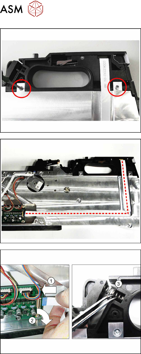
► Place the feeder module carefully down on its
right side.
► Fasten the handle using the two marked screws
with 0.6Nm.
► Fold the flat ribbon cable in exactly the same way
as the old cable.
► Run the cable as shown and press the cable into
the cable duct and onto the double-sided adhes-
ive tape. Replace the adhesive tape if necessary.
When running the cable, make sure that the blue
side points upwards at the end of the cable.
► Insert the end of the flat ribbon cable (with the
blue side pointing upwards) up to the stop in the
flat ribbon connection shown on the control
board.(1)
► Close the connection and make sure that the
cable it firmly fitted.(2)
► Fit the two compression springs into the
rocker.(3)
► Fasten the left and the right side covers (see
9.3.2 "Fitting the Left Side Cover" [}184], 9.3.4
"Fitting the Right Side Cover" [}185]).
9.14 Control board
The control board for the SmartFeeder 2x8mmX is not available as a spare part, because the cali-
bration data for the pickup position are saved in the EEPROM of this board.
A new calibration of the pickup position is therefore only possible at the final inspection point of the
feeder module production at ASM.