00198505-01_SM_SIPLACE_SmartFeeder_EN.pdf - 第245页
10 Repairs to SmartFeeder 24 - 104 mm X 10.6 Splice sensor Service Manual SIPLACE SmartFeeder 4 - 104 mm X 11/2017 245 ► Place the feeder module in a stable, upright posi- tion. ► Loosen the Phillips screw shown in the d…
10 Repairs to SmartFeeder 24 - 104 mm X
10.6 Splice sensor
244 Service Manual SIPLACE SmartFeeder 4 - 104 mm X 11/2017
10.6.3 Filler piece
NOTICE
Filler piece = connection for the splice sensor
In the SmartFeeder X, the splice sensor is not connected via its own cable but via a contact
board in the filler piece which is connected to the feeder module.
The connection cable is not available as a separate spare part. If there is a defect on the
connection cable, the entire filler piece will need to be replaced.
Required spare part
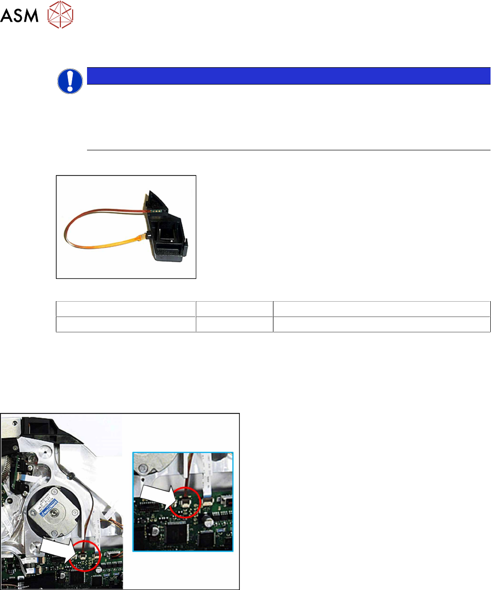
Fig.88: Filler piece splice sensor assy. X24-104
Feeder module Item no. Designation
SmartFeeder 24 - 104mmX 03115816-xx Filler piece splice sensor assy. X24-104
Required tools
●
Phillips screwdriver 0.6Nm
●
Tweezers
10.6.3.1 Removing the filler piece
► Remove the left side plate (see 10.3.1 "Remov-
ing/fitting the left side plate" [}230]).
► Unplug the connector for the splice sensor cable
from the connection on the control board.
10 Repairs to SmartFeeder 24 - 104 mm X
10.6 Splice sensor
Service Manual SIPLACE SmartFeeder 4 - 104 mm X 11/2017 245
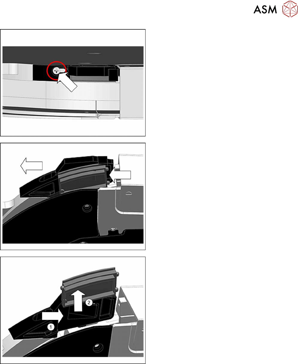
► Place the feeder module in a stable, upright posi-
tion.
► Loosen the Phillips screw shown in the diagram,
until the filler piece can be moved.
► Carefully push the filler piece in the direction of
the arrow, as far as the stop.
► Push the splice sensor (-dummy) to the right and
out of the filler piece.(1)
► Lift the splice sensor (-dummy) up and out.(2)
► Remove the filler piece.
10 Repairs to SmartFeeder 24 - 104 mm X
10.6 Splice sensor
246 Service Manual SIPLACE SmartFeeder 4 - 104 mm X 11/2017
10.6.3.2 Fitting the filler piece
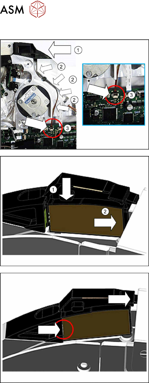
► Carefully place the feeder module with the right
side down on a stable, level and clean surface.
► Place the filler piece as shown on the feeder
module.(1)
► Run the splice sensor cable as marked in the dia-
gram, in the cable duct.(2)
► Plug the connector for the splice sensor cable
into the connection on the control board.(3)
► Place the feeder module in a stable, upright posi-
tion.
► Lift the splice sensor (dummy) as shown into the
filler piece.(1)
Make sure that the 2 fixing pins point to the front
and the 3 contact pins to the back.
► Push the splice sensor (dummy) with the fixing
pins first as far as the stop, in the direction of the
arrow: to the right.(2)
► Push the filler piece as far as the stop to the right
(direction of the arrow).
When fitting the splice sensor, make sure that the
contact pins of the sensor touch the contacts on
the filler piece.