00198505-01_SM_SIPLACE_SmartFeeder_EN.pdf - 第148页
8 Repairs to SmartFeeder 2x8 mm X 8.6 Splice sensor / dummy 148 Service Manual SIPLACE SmartFeeder 4 - 104 mm X 11/2017 ► Lower the dummy sensor completely down. ► Push the dummy sensorforwards, in the direction of the …
8 Repairs to SmartFeeder 2x8 mm X
8.6 Splice sensor / dummy
Service Manual SIPLACE SmartFeeder 4 - 104 mm X 11/2017 147
8.6.4 Fitting the Dummy Splice Sensor
CAUTION
During assembly, make sure that the cable is not wedged in between the base unit, the
dummy splice sensor and the side covers.
► Place the feeder module down on a stable sur-
face e.g. a single slot EDIF or place the feeder
module on a level and clean surface.
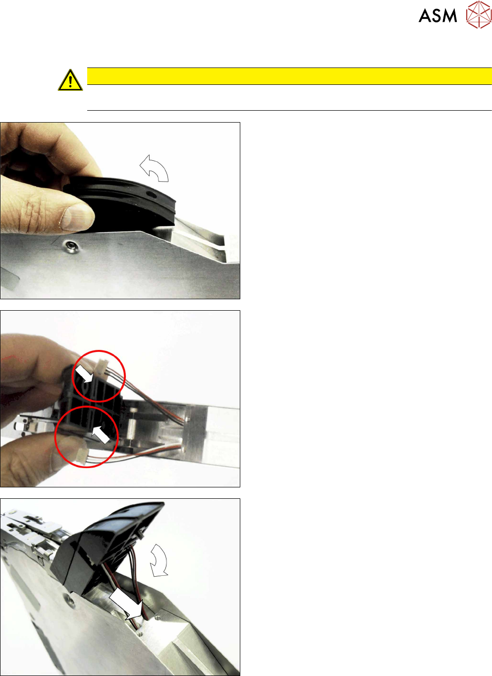
► Place the dummy sensor next to the tape duct, as
shown in the diagram.
► Swing the dummy sensor up with the tip pointing
upwards.
► Pull the cable about 4 cm out of the base unit of
the feeder module.
► Push the cable connector from the outside, side-
ways into the dummy sensor guidance.
Make sure that the cable is pushed into the
dummy sensor on the correct side, as shown.
► Push the cable into each left and right cable duct
in the base unit of the feeder module.
► Carefully swing the dummy sensor down.
Make sure that the cable is not wedged in
between the base unit, the dummy splice sensor
and the side covers.
8 Repairs to SmartFeeder 2x8 mm X
8.6 Splice sensor / dummy
148 Service Manual SIPLACE SmartFeeder 4 - 104 mm X 11/2017
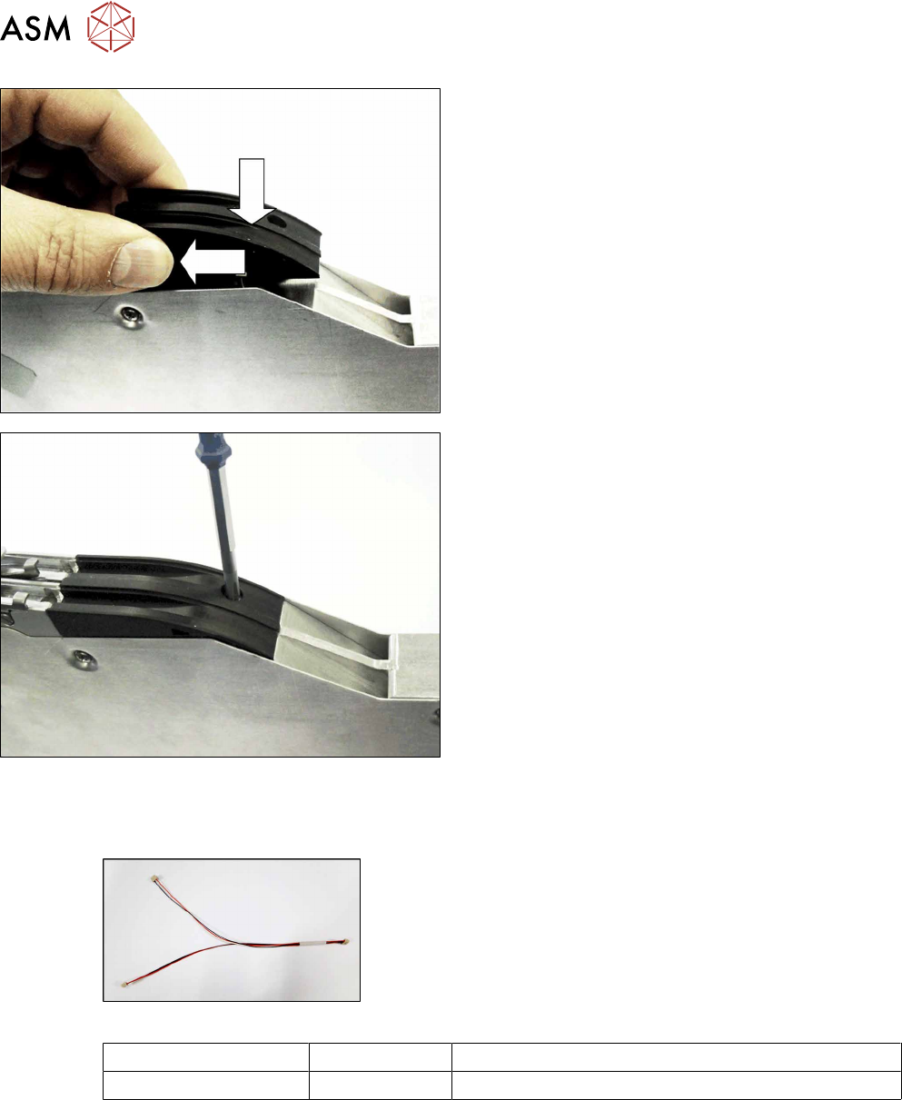
► Lower the dummy sensor completely down.
► Push the dummy sensorforwards, in the direction
of the arrow, as far as the stop.
► Fasten the dummy sensor with a screw (M2,
5x6).
Use a Phillips screwdriver for this.
8.6.5 Cable splice sensor
Required spare parts
Fig.46: Cable splice sensor
Feeder module Item no. Designation
2x8mm X 03063593- xx Cable for splice sensor X2x8
Required tools
●
Phillips screwdriver
●
TORX screwdriver size T8
8 Repairs to SmartFeeder 2x8 mm X
8.6 Splice sensor / dummy
Service Manual SIPLACE SmartFeeder 4 - 104 mm X 11/2017 149
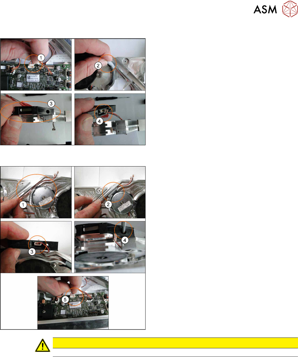
8.6.5.1 Removing the Cable Splice Sensor
► Place the feeder on a stable, level and clean sur-
face.
► Remove the left and right side covers. (See 8.3.1
"Removing the Left Side Cover" [}135], 8.3.3
"Removing the Right Side Cover" [}136])
► Disconnect the connector from the main
board(1).
► Remove the seal band left and right(2).
► Remove the M2.5x6 screw from splice sensor(3)
and disconnect the cables(4).
8.6.5.2 Fitting the Cable Splice Sensor
► Lay the new cables(1).
► Place the seal band left and right level with the
channel. Ensure the cables can move freely.(2).
► Reconnect the cables to the splice sensor(3).
► Refit the splice sensor using the M2 5x6
screw(4).
► Connect the connector to the main board(5).
► Fit the left and right side covers. (See 8.3.2 "Fit-
ting the Left Side Cover" [}136], 8.3.4 "Fitting the
Right Side Cover" [}137])
CAUTION
Ensure the cables are not trapped between housing, splice sensor and covers.