00198505-01_SM_SIPLACE_SmartFeeder_EN.pdf - 第164页
8 Repairs to SmartFeeder 2x8 mm X 8.8 Foil rocker 164 Service Manual SIPLACE SmartFeeder 4 - 104 mm X 11/2017 8.8 Foil rocker 8.8.1 Foil rocker assembly Required spare part Fig.52: Foil rocker assembly Fig.53: Cable li…
8 Repairs to SmartFeeder 2x8 mm X
8.7 Drives
Service Manual SIPLACE SmartFeeder 4 - 104 mm X 11/2017 163
8.7.3.2 Fitting the hybrid stepping motor assembly
NOTICE
The installation procedure is the same for the left and right lane.
This section describes the installation of the hybrid stepping motor on the left side (lane 1).
The installation procedure for the hybrid stepping motor on the right side (lane 2) is the
same, except that it is laterally reversed.
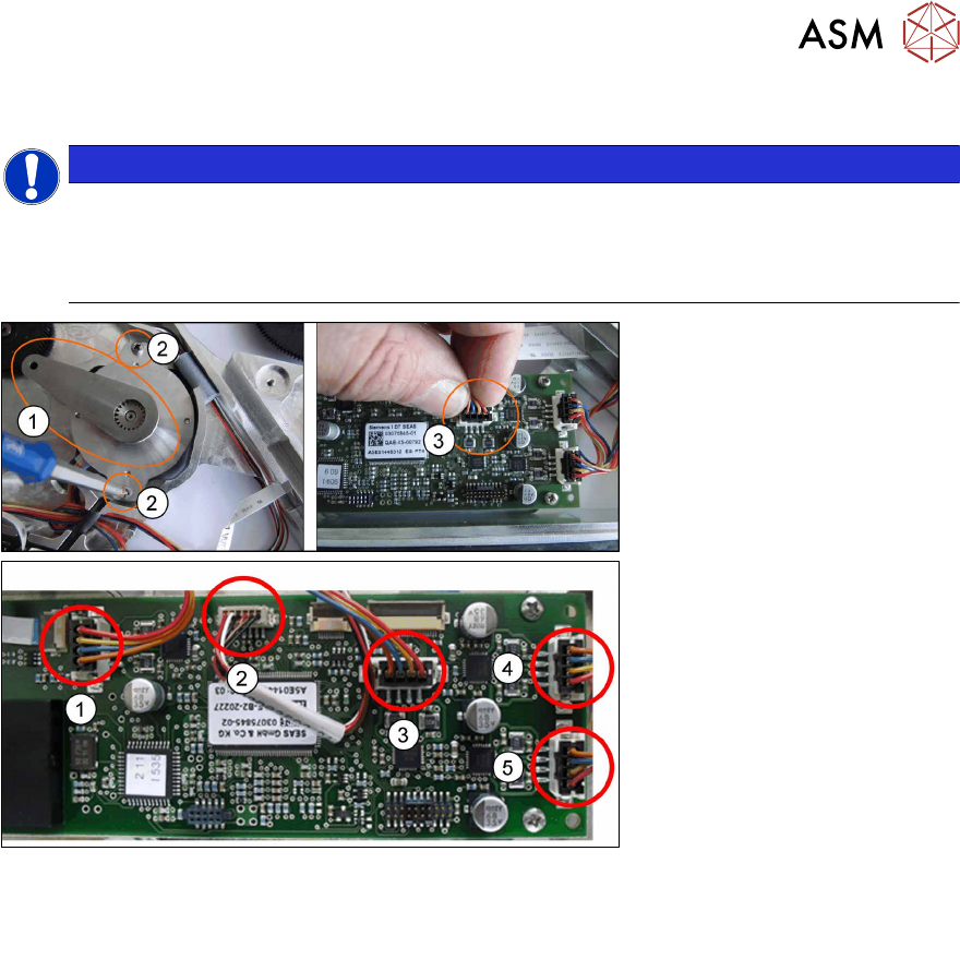
Fig.51: Overview of connections on the control board
1. Tape drive left lane (lane 1) 3. Foil drive left lane (lane 1)
2. Tape drive right lane (lane 2) 4. Foil drive right lane (lane 2)
► Place the hybrid stepping motor in position and run the cable through the housing.
► Fit the gauge for the tape motor(1).
► Use the two Phillips screws marked in the diagram to fasten the motor to 0.9Nm. (2)
► Remove the gauge.
► Plug the motor cable connector into the relevant connection on the control board e.g. for the
foil drive of the left lane (lane 1).(3)
Select the connection which matches the motor from the "Overview of connections on the
control board" shown above.
► Refit the shifted gear (see 8.7.1.2 "Fitting the shifted gear 1 left / right tape" [}151]).
► Fasten the left side covers (see 8.3.2 "Fitting the Left Side Cover" [}136]).
8 Repairs to SmartFeeder 2x8 mm X
8.8 Foil rocker
164 Service Manual SIPLACE SmartFeeder 4 - 104 mm X 11/2017
8.8 Foil rocker
8.8.1 Foil rocker assembly
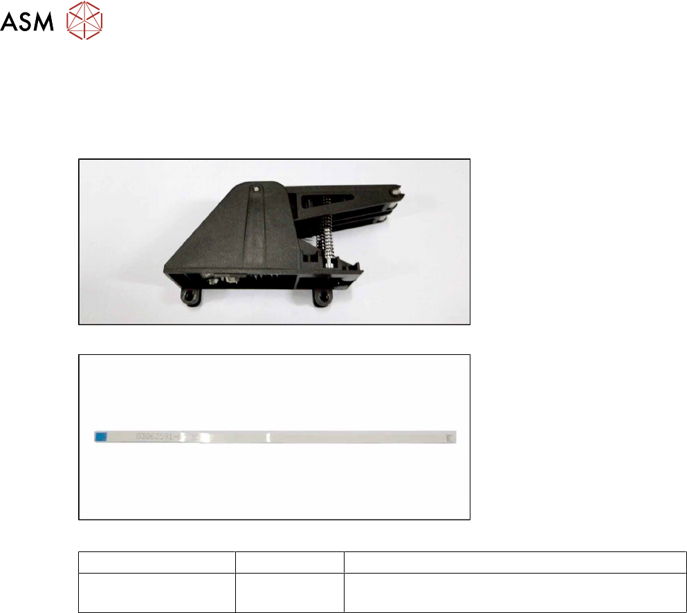
Required spare part
Fig.52: Foil rocker assembly
Fig.53: Cable light barrier transmitter
Feeder module Item no. Designation
SmartFeeder 2x8mmX 03066480-xx
03063591-xx
Foil rocker assembly /X2x8
Cable light barrier transmitter
Required tools
●
TORX screwdriver 0.6Nm, size T8
●
Small flat-bladed screwdriver
8 Repairs to SmartFeeder 2x8 mm X
8.8 Foil rocker
Service Manual SIPLACE SmartFeeder 4 - 104 mm X 11/2017 165
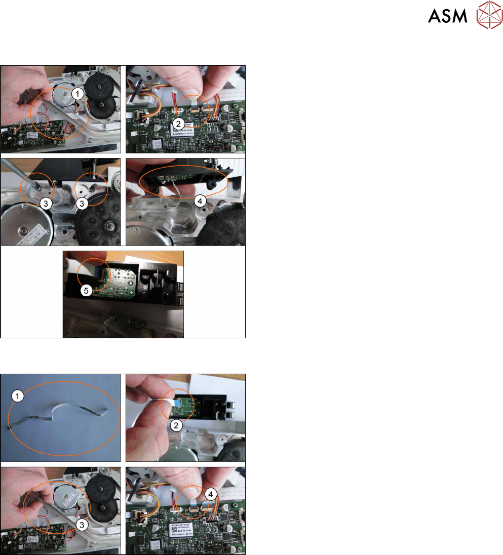
8.8.1.1 Removing the Foil Rocker Cpl.
► Place the feeder on a stable, level and clean sur-
face.
► Remove the left and right side covers. (See 8.3.1
"Removing the Left Side Cover" [}135], 8.3.3
"Removing the Right Side Cover" [}136])
► Remove the tape duct.(1)
► Unplug the photo interrupter cable from the main
board.(2)
► Loosen and remove the TORX screws from the
foil rocker.(3)
► Push the foil rocker to the right(4) and unplug the
cable.(5)
8.8.1.2 Fitting the Foil Rocker Cpl.
► Fasten the new cable at the same positions as
the old cable.(1)
► Connect the cable to the foil rocker connector
and then fit the foil rocker.(2)
► Replace the tape duct, making sure that the
cable is at the bottom.(3)
► Connect the cable to the main board. (4)
► Refit the left and right side covers (see 8.3.2 "Fit-
ting the Left Side Cover" [}136], 8.3.4 "Fitting the
Right Side Cover" [}137]).