00198505-01_SM_SIPLACE_SmartFeeder_EN.pdf - 第196页
9 Repairs to SmartFeeder 12 mm X / 16 mm X 9.6 Splice Sensor 196 Service Manual SIPLACE SmartFeeder 4 - 104 mm X 11/2017 9.6.3 Splice Sensor Cable NOTICE Splice sensor or dummy The feeder module can be fitted with either…
9 Repairs to SmartFeeder 12 mm X / 16 mm X
9.6 Splice Sensor
Service Manual SIPLACE SmartFeeder 4 - 104 mm X 11/2017 195
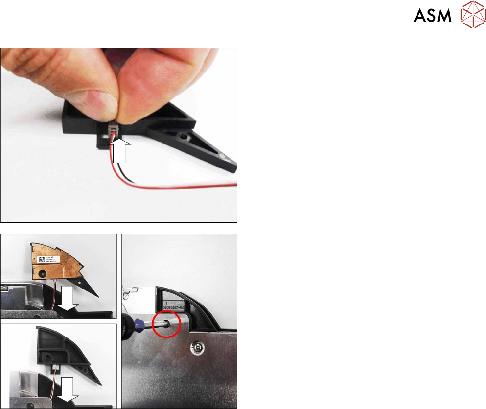
For the splice sensor dummy:
► Insert the 4-pin connector for the splice sensor
cable onto the splice sensor dummy, as shown in
the diagram.
► Push the splice sensor cable and the splice
sensor (dummy) back into the feeder module
housing.
► Fix the splice sensor (dummy) with the marked
screw. Use a Phillips screwdriver with 0.6 Nm for
this.
9 Repairs to SmartFeeder 12 mm X / 16 mm X
9.6 Splice Sensor
196 Service Manual SIPLACE SmartFeeder 4 - 104 mm X 11/2017
9.6.3 Splice Sensor Cable
NOTICE
Splice sensor or dummy
The feeder module can be fitted with either a splice sensor or a dummy splice sensor. The
procedure is the same in both cases.
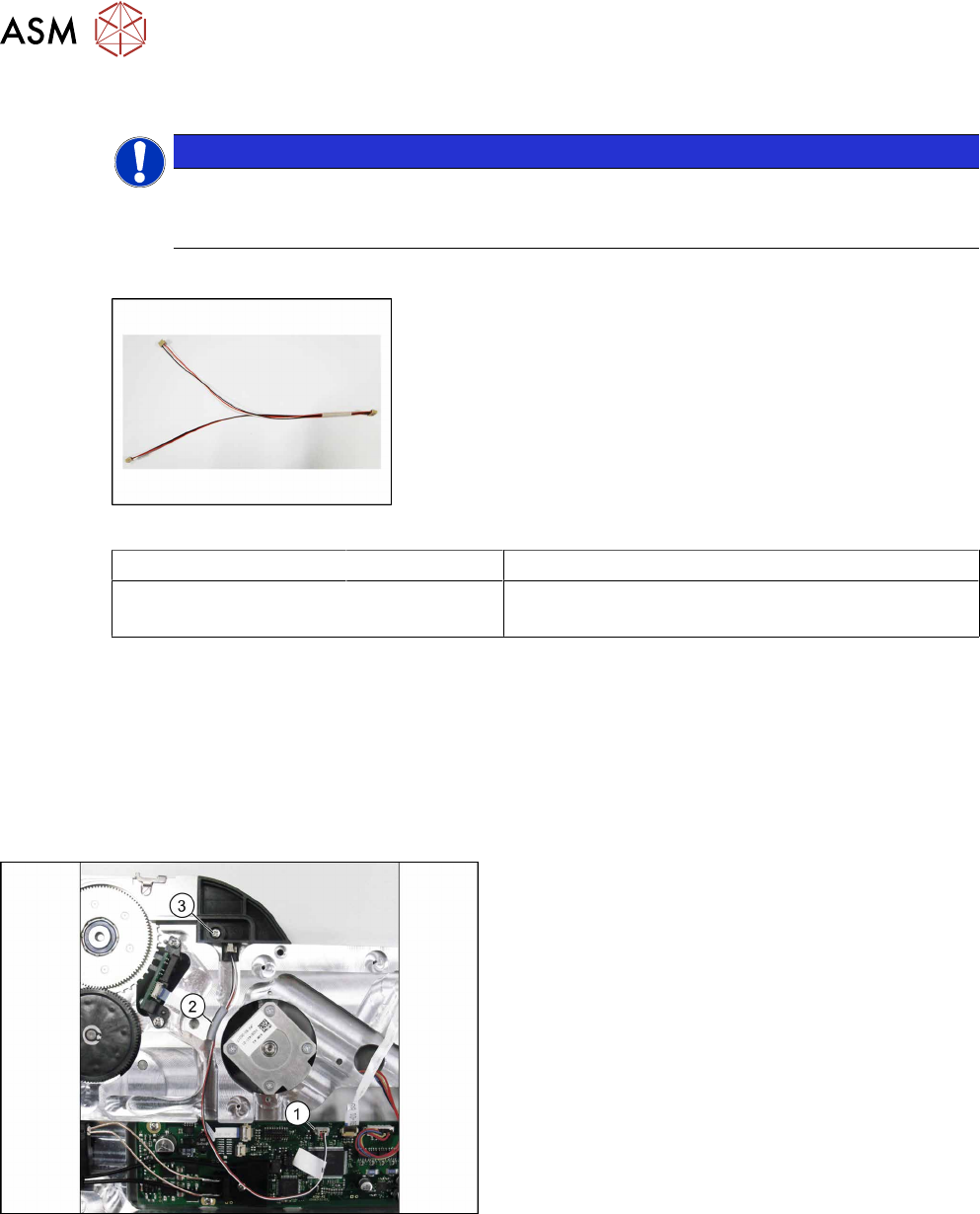
Required spare parts
Fig.68: Cable splice sensor
Feeder module Item no. Designation
SmartFeeder 12 mm X
SmartFeeder 16 mm X
03081962- xx Cable for splice sensor X12/X16 V2
Required tools
●
Slotted screwdriver size 1
●
Phillips screwdriver 0.6Nm
●
TORX screwdriver 0.6Nm, size T8
●
Tweezers
9.6.3.1 Removing the Splice Sensor Cable
► Remove the left side cover (see 9.3.1 "Removing
the Left Side Cover" [}184]).
► Unplug the splice sensor cable from the connec-
tion on the control board.(1)
► Remove the cover cord (rubber) from the cable
duct. (2)
► Remove the marked screw from the splice sensor
(dummy).(3)
► Remove the splice sensor or splice sensor
dummy.
9 Repairs to SmartFeeder 12 mm X / 16 mm X
9.6 Splice Sensor
Service Manual SIPLACE SmartFeeder 4 - 104 mm X 11/2017 197
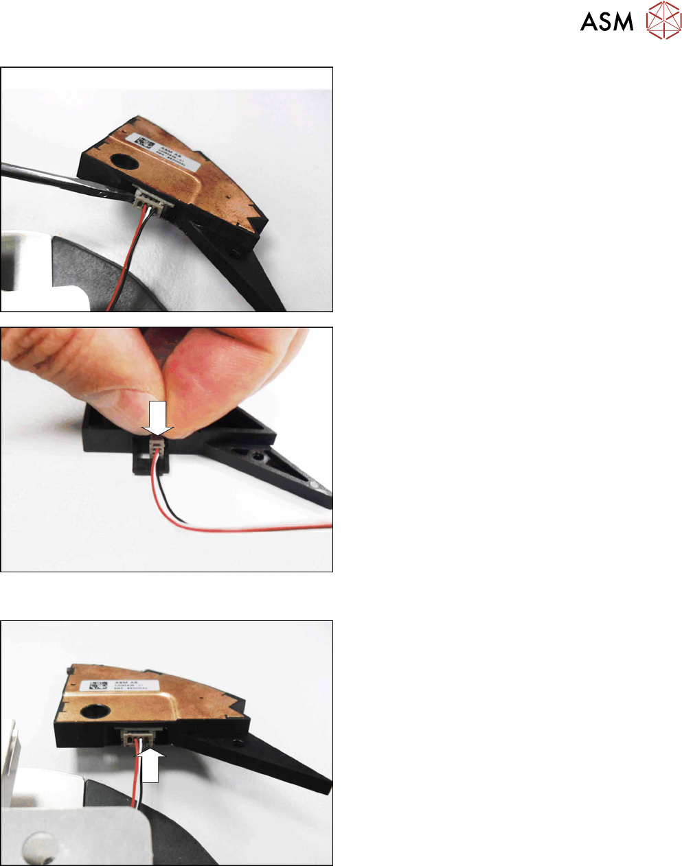
For the splice sensor:
► Carefully lever the connector of the splice sensor
cable out of the connection. Use a small screw-
driver or pair of tweezers to help you.
For the splice sensor dummy:
► Pull the splice sensor cable out of the splice
sensor dummy.
9.6.3.2 Fitting the Cable Splice Sensor
For the splice sensor:
► Fit the 4-pin connector for the splice sensor cable
into the splice sensor, as shown in the diagram.