00198505-01_SM_SIPLACE_SmartFeeder_EN.pdf - 第279页
10 Repairs to SmartFeeder 24 - 104 mm X 10.13 Handle assembly with control panel Service Manual SIPLACE SmartFeeder 4 - 104 mm X 11/2017 279 10.13 Handle assembly with control panel Required spare part Fig.102: Handle X…
10 Repairs to SmartFeeder 24 - 104 mm X
10.12 Leaf spring
278 Service Manual SIPLACE SmartFeeder 4 - 104 mm X 11/2017
10.12 Leaf spring
Required spare part
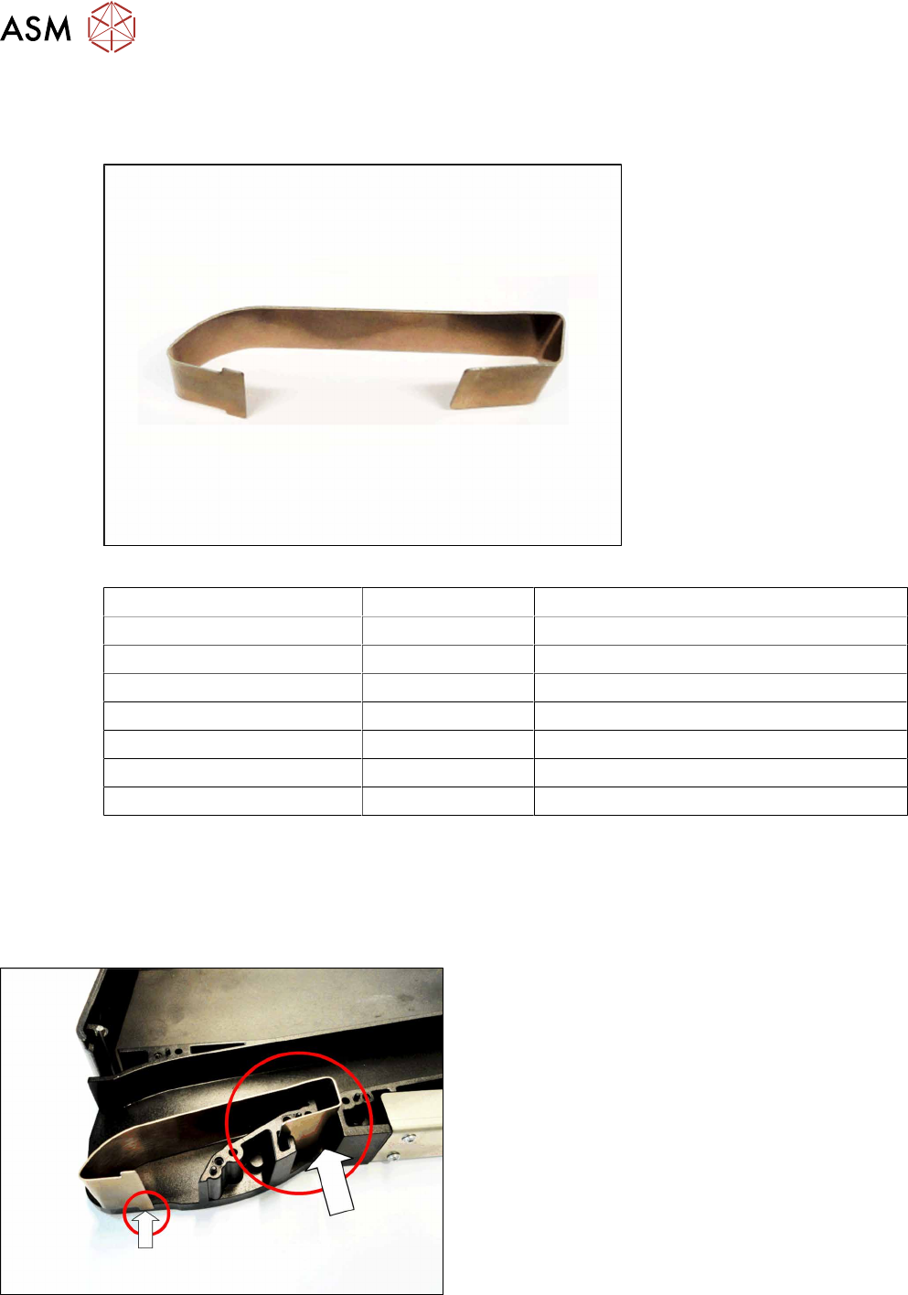
Fig.101: Leaf spring tape infeed
Feeder module Item no. Designation
SmartFeeder 24mm X 03115906Sxx Leaf spring tape infeed X24Smart
SmartFeeder 32mm X 03117180-xx Leaf spring tape infeed X32Smart
SmartFeeder 44mm X 03120864-xx Leaf spring tape infeed X44Smart
SmartFeeder 56mm X 03120622-xx Leaf spring tape infeed X56Smart
SmartFeeder 72mm X 03116123-xx Leaf spring tape infeed X72Smart
SmartFeeder 88mm X 03121027-xx Leaf spring tape infeed X88Smart
SmartFeeder 104mm X 03121157-xx Leaf spring tape infeed X104Smart
Required tools
●
Phillips screwdriver 0.6Nm
●
TORX screwdriver 0.6Nm, size T8
10.12.1 Replacing the leaf spring
► Carefully place the feeder module with the left
side down on a stable, level and clean surface.
► Remove the right side wall (see 10.3.3 "Rear side
wall on the right" [}231])
► Pull the leaf spring up and out of the feeder mod-
ule base unit.
► Insert the new leaf spring, as shown, into the
base unit.
Make sure that the lower catch for the leaf spring
(marked on the left in the diagram) is outside the
base unit.
► Fasten the right side wall (see 10.3.3 "Rear side
wall on the right" [}231])
10 Repairs to SmartFeeder 24 - 104 mm X
10.13 Handle assembly with control panel
Service Manual SIPLACE SmartFeeder 4 - 104 mm X 11/2017 279
10.13 Handle assembly with control panel
Required spare part
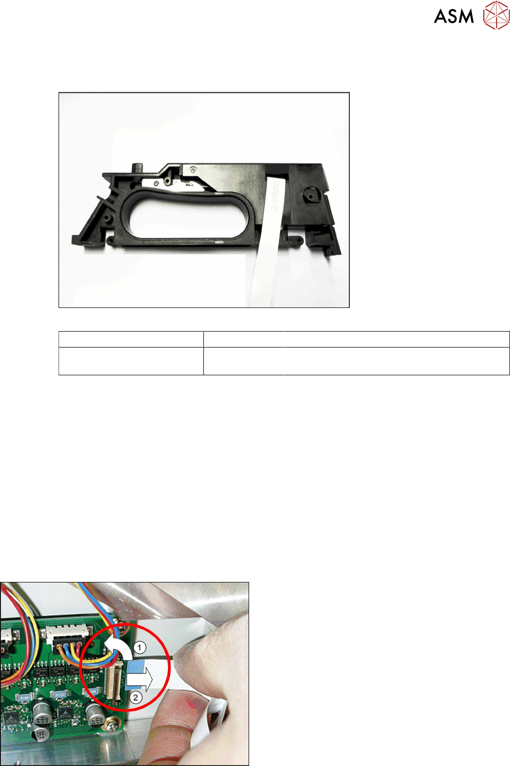
Fig.102: Handle X24-104 assy.
Feeder module Item no. Designation
SmartFeeder 24 – 104 mm X 03112666Sxx Handle assembly X24-104.
(prefitted with flat ribbon cable)
Required tools
●
Phillips screwdriver 0.6Nm
●
TORX screwdriver size T8, 0.6Nm
●
Tweezers
10.13.1 Removing the handle assembly
► Carefully place the feeder module with the left side down on a stable, level and clean surface.
► Remove the right side wall (see 10.3.3 "Rear side wall on the right" [}231])
► Remove the pressure spring from the rocker (see 10.9.2.1 "Replacing the pressure spring and
spring support" [}271]).
► Carefully place the feeder module with the right side down on a stable, level and clean sur-
face.
► Remove the left side plate (see 10.3.1 "Removing/fitting the left side plate" [}230]).
► Open the bar on the flat ribbon connection on the
control board.(1)
► Unplug the flat ribbon cable form the connec-
tion.(2)
10 Repairs to SmartFeeder 24 - 104 mm X
10.13 Handle assembly with control panel
280 Service Manual SIPLACE SmartFeeder 4 - 104 mm X 11/2017
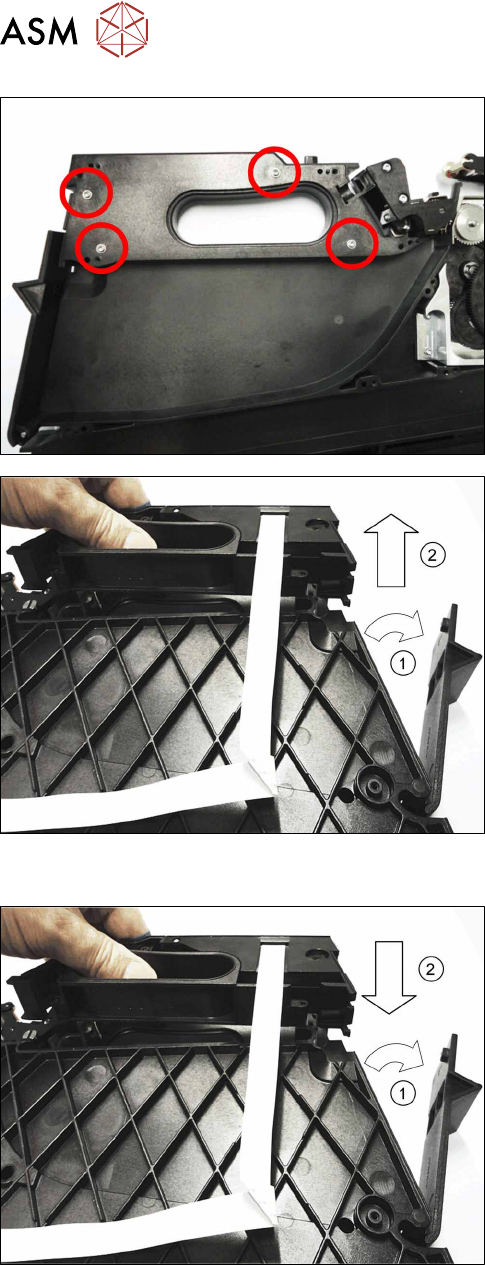
► Carefully place the feeder module with the left
side down on a stable, level and clean surface.
► Remove the four screws marked in the diagram,
which are fastening the handle. Use a size T8
TORX screwdriver for this.
► Carefully place the feeder module with the right
side down on a stable, level and clean surface.
► Open the tape container flap.(1)
► Lift the handle straight up and out of the feeder
module base unit. (2)
10.13.2 Fitting the handle assembly
► Carefully place the feeder module with the right
side down on a stable, level and clean surface.
► Open the flap on the foil container.(1)
► Insert the handle straight down and into the
feeder module base unit. (2)
► Close the flap on the foil container.