00198505-01_SM_SIPLACE_SmartFeeder_EN.pdf - 第98页
7 Repairs to SmartFeeder 8 mm X 7.7 Drives 98 Service Manual SIPLACE SmartFeeder 4 - 104 mm X 11/2017 7.7.1.1 Removing the Foil Disposal Motor ► Carefully place the feeder module with the right side down on a stable, lev…
7 Repairs to SmartFeeder 8 mm X
7.7 Drives
Service Manual SIPLACE SmartFeeder 4 - 104 mm X 11/2017 97
7.7 Drives
7.7.1 Foil motor
Required spare part
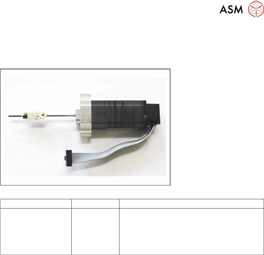
Fig.29: Motor coupling/foil disposal X-Series
Feeder module Item no. Designation
SmartFeeder 8mm X 03050686Sxx
03028610-xx
03012488-xx
03042536-01
Motor coupling/foil disposal X-Series
Bearing block, ceramic
SN 213307-H-M2 x 2.5-A2
(for fitting the bearing block)
ISO 4762 - M 2.5 x 12-A2-70
(for fitting the motor)
Required tools
●
Phillips screwdriver 0.9Nm
●
Flat-bladed screwdriver size 3
●
TORX screwdriver 0.6Nm, size T8
●
Angled Allen key, size 2
●
Allen key 0.9 Nm, size 4
●
Tweezers
Required consumables
●
Grease Klübersynth GE 14-151
7 Repairs to SmartFeeder 8 mm X
7.7 Drives
98 Service Manual SIPLACE SmartFeeder 4 - 104 mm X 11/2017
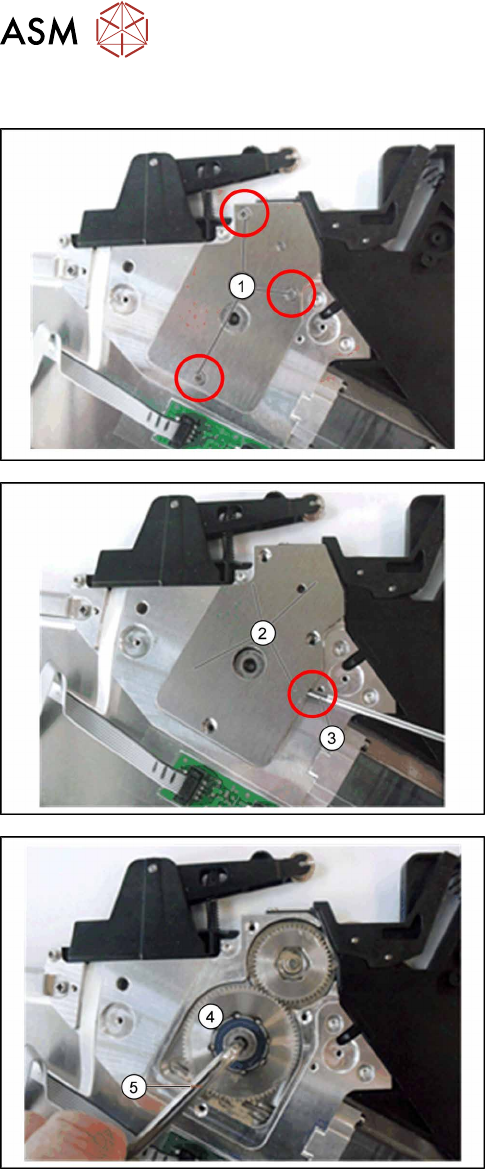
7.7.1.1 Removing the Foil Disposal Motor
► Carefully place the feeder module with the right
side down on a stable, level and clean surface.
► Remove the left side cover (see 7.3.1 "Removing
the Left Side Cover" [}83]).
► Remove the 3 Phillips screws(1) marked in the
diagram from the bearing cap for the foil gear.
► Lift the bearing cap(2) up with a pair of tweezers
or a small screwdriver(3) and remove it.
► Loosen the spiral gear(4) on the foil disposal
with a size 4 Allen key(5).
7 Repairs to SmartFeeder 8 mm X
7.7 Drives
Service Manual SIPLACE SmartFeeder 4 - 104 mm X 11/2017 99
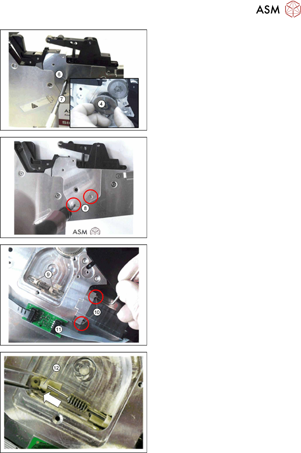
► Move the feeder module to an upright and stable
position.
On the right-hand side of the feeder module you can
access the bearing screw (6) for the spiral gear.
► On the left-hand side of the feeder module, you
can hold the spiral gear(4), while on the right-
hand side, you can open the connection using a
size 3 slotted screwdriver(7).
► Pull the spiral gear(4) off completely.
► Remove the two screws(8), with which the
ceramic bearing blocks(9) are fixed on the other
side.
► Turn the feeder module on to its right side.
► Open the two screws(10), with which the motor
is fastened. Use a size 2 angled Allen key for
this.
► Pull the motor cable connector(11) out of the
coupling board.
► Use a pair of tweezers to pull the outer bearing
block(12) off the motor shaft.