00198505-01_SM_SIPLACE_SmartFeeder_EN.pdf - 第86页
7 Repairs to SmartFeeder 8 mm X 7.4 EDIF 86 Service Manual SIPLACE SmartFeeder 4 - 104 mm X 11/2017 7.4 EDIF Required spare part Fig.25: EDIF secondary assembly Feeder module Item no. Designation SmartFeeder 8mmX (V1)…

7 Repairs to SmartFeeder 8 mm X
7.3 Side Covers
Service Manual SIPLACE SmartFeeder 4 - 104 mm X 11/2017 85
7.3.4 Fitting the right side cover 8
► Carefully place the feeder module with the left
side down on a stable, level and clean surface.
► Connect the motor connector for the foil disposal
(1) to the left connection for the coupling board
(3).
► Plug the connector from the control board (2) into
the right connection on the coupling board (3).
Observe the correct position of the foam seal (1).
Make sure that the foam seal does not get trapped in
the empty tape duct (2) or protrude into it!
To check the correct position of the foam seal, remove
the left side cover, as shown (after fitting the right side
cover), and correct the position of the foam rubber if
necessary.
► Insert the side cover (in the area marked red), as
shown, under the rail, as far as the stop.
► Insert the side cover on the right side, in the area
marked yellow under the encoder.
► Fasten the screws as shown in the diagram. Be-
gin with the inner screws (C) and work towards
the outside (B + A).
The screw marked Eshould be fastened last.
You need a Phillips screwdriver with 0.6 Nm for the
screws marked B and C.
You need a TORX screwdriver with 0.6 Nm for the
screws marked A.
Also use a TORX screwdriver for the screw marked D.
CAUTION!
Tighten screw E no more than hand-tight, other-
wise the screw fixtures inside the feeder module
could be damaged or broken.
.
7 Repairs to SmartFeeder 8 mm X
7.4 EDIF
86 Service Manual SIPLACE SmartFeeder 4 - 104 mm X 11/2017
7.4 EDIF
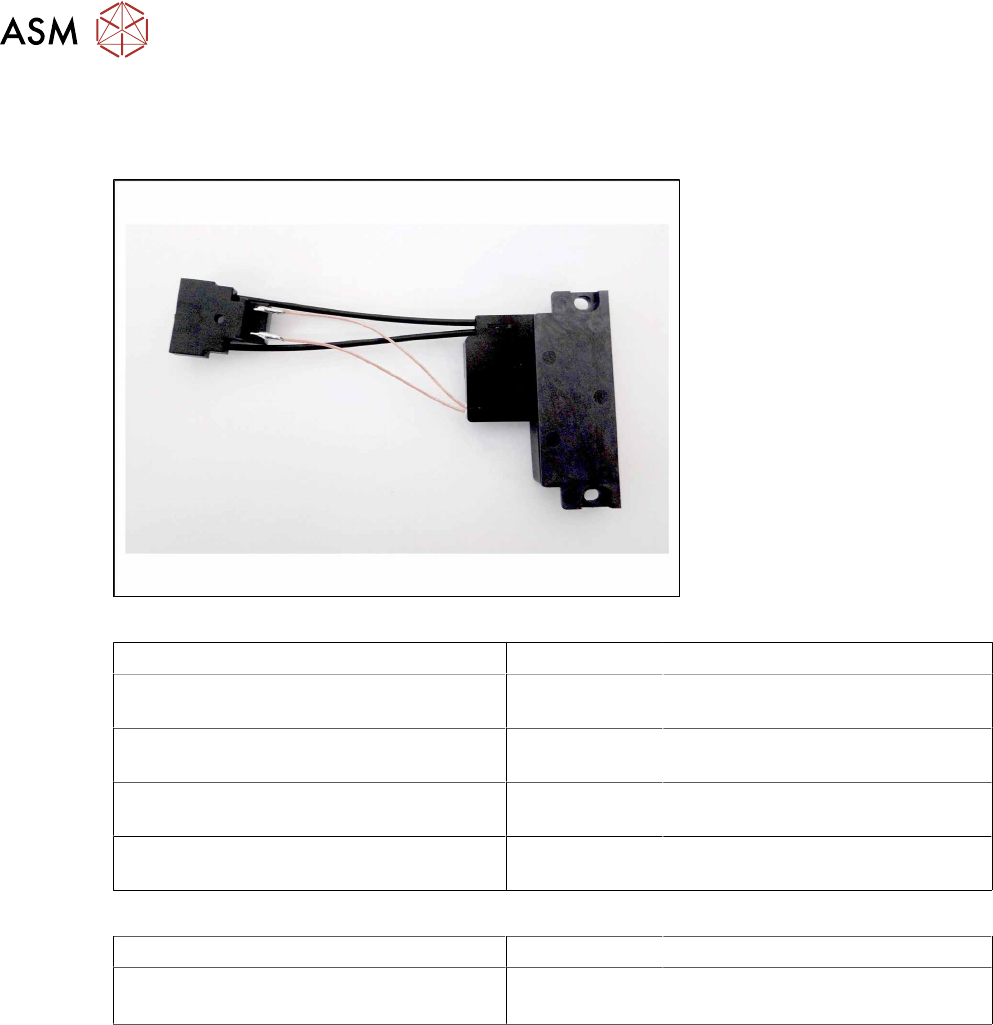
Required spare part
Fig.25: EDIF secondary assembly
Feeder module Item no. Designation
SmartFeeder 8mmX (V1)
00141370-01
03101192Sxx EDIF secondary assembly X8Smart
SmartFeeder 8mmX (V2)
00141370-02
03127518- EDIF secondary assembly X8Smart
SmartFeeder 8mm X splice sensor (V1)
00141390-01
03101192Sxx EDIF secondary assembly X8Smart
SmartFeeder 8mm X splice sensor (V2)
00141390-02
03127518-xx EDIF secondary assembly X8Smart
Other spare parts:
Feeder module Item no. Designation
All feeder modules mentioned in the above
table.
03012683-xx
03050957-xx
Pressure spring D-027
Collar screw D4x3.15 M3
Required tools
●
Flat-bladed screwdriver 0.9Nm
●
Phillips screwdriver 0.9Nm
●
TORX screwdriver 0.6Nm, size T8
7 Repairs to SmartFeeder 8 mm X
7.4 EDIF
Service Manual SIPLACE SmartFeeder 4 - 104 mm X 11/2017 87
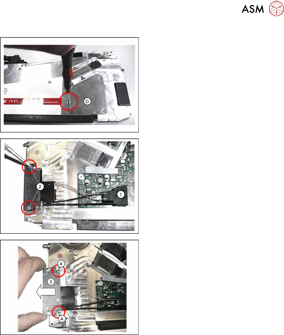
7.4.1 Removing the EDIF
► Carefully place the feeder module with the left
side down on a stable, level and clean surface.
► On the right side plate, only remove screwD, in
order to release the EDIF connector in the feeder
module.
► Remove the left side cover (see section 7.3.1
"Removing the Left Side Cover" [}83]).
► Pull the EDIF connector(1) straight up and off
the board.
► Loosen the two screws on the EDIF.(2)
► Remove the EDIF.(3)
► Remove the two pressure springs. (4)