00198505-01_SM_SIPLACE_SmartFeeder_EN.pdf - 第45页
6 Repairs to SmartFeeder 4 mm X 6.7 Drives Service Manual SIPLACE SmartFeeder 4 - 104 mm X 11/2017 45 ► Use tweezers to carefully push the outer bearing block (4) onto the motor shaft. ► Apply a little grease to the wor…
6 Repairs to SmartFeeder 4 mm X
6.7 Drives
44 Service Manual SIPLACE SmartFeeder 4 - 104 mm X 11/2017
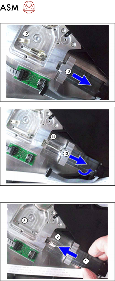
► Carefully pull the motor(13) straight off the foil
disposal unit.
Make sure that the motor shaft is not bent when
pulled out.
► Lift the motor(13) somewhat at the back and pull
it completely out of the foil disposal unit, together
with its worm gear and the inner bearing
block(14).
6.7.1.2 Fitting the Foil Disposal Motor
► Carefully place the feeder module with the right
side down on a stable, level and clean surface.
► Push the replacement motor(1) with worm gear
and inner bearing block(2) carefully into the foil
stripping unit(3).
► When pushing it in, make sure that the motor
shaft is not bent.
6 Repairs to SmartFeeder 4 mm X
6.7 Drives
Service Manual SIPLACE SmartFeeder 4 - 104 mm X 11/2017 45
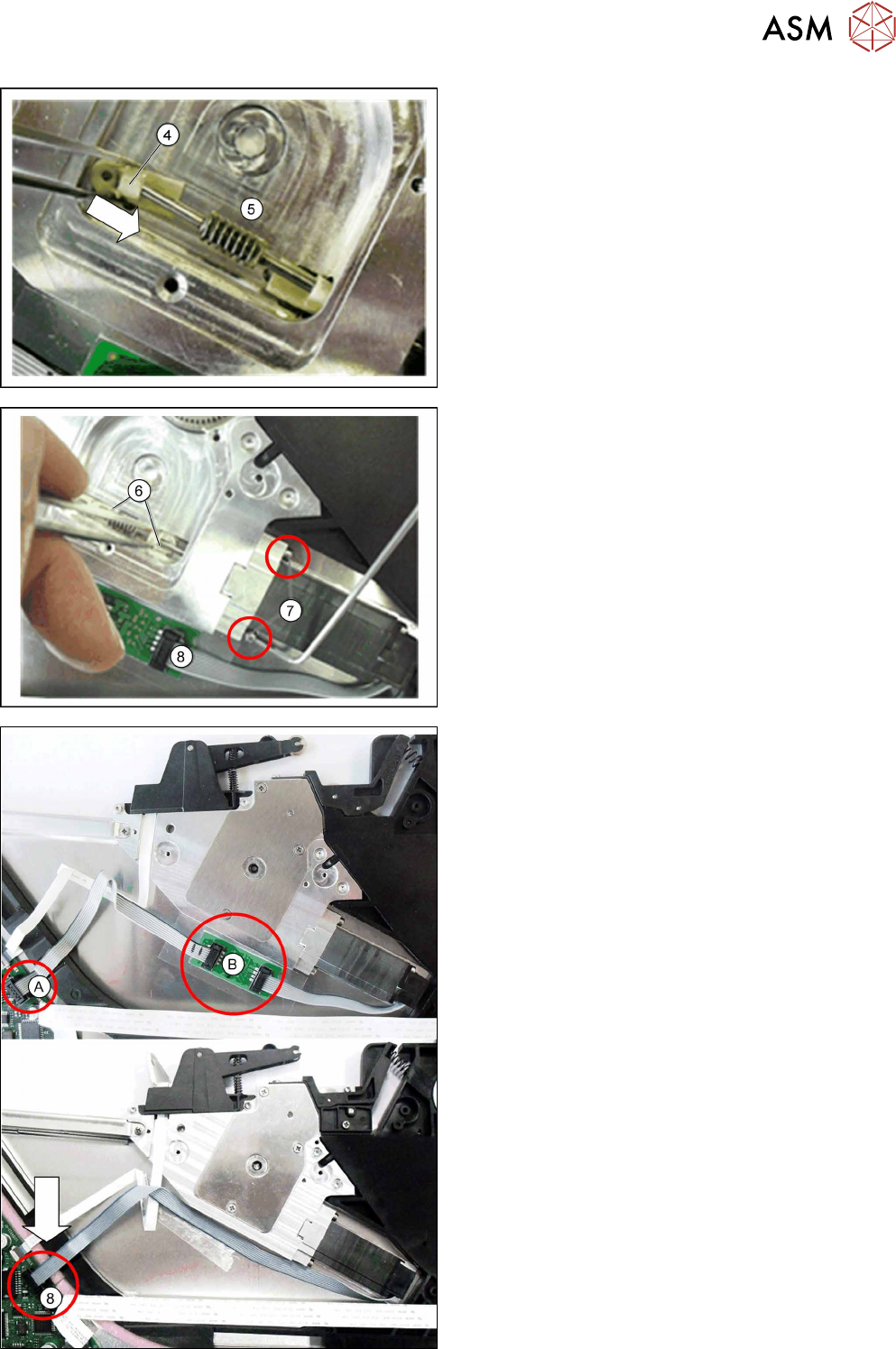
► Use tweezers to carefully push the outer bearing
block(4) onto the motor shaft.
► Apply a little grease to the worm gear(5).
Use Klübersynth GE14-151 for this.
► Push the two bearing block assys(6) into the
position shown.
► Fasten the motor with the two Allen screws
marked(7). Use a size 2 angled Allen key for this
(hand-tighten).
► Apply a little grease to the bearing block as-
sys(6).
Use Klübersynth GE14-151 for this.
► Insert the connector for the motor cable into the
connection on the coupling board.(8)
For replacement motors with long motor cable
In older versions of the SmartFeeder 8 mm X, motors
with a short connection cable were used with a coup-
ling board and extension cable.
The new replacement motors have a longer motor
cable to establish a direct connection from the motor
to the control board. The coupling board is therefore
no longer needed in these cases and can be removed.
The motor cable is then directly connected to the con-
trol board.
► Unplug the extension cable from the connection
on the control board.(A)
► Remove the motor coupling board.(B)
► Insert the motor cable connector into the connec-
tion on the control board. (8)
6 Repairs to SmartFeeder 4 mm X
6.7 Drives
46 Service Manual SIPLACE SmartFeeder 4 - 104 mm X 11/2017
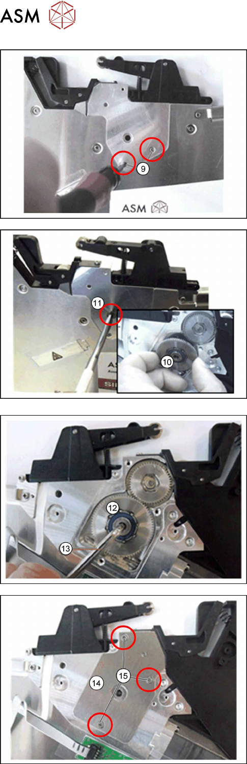
► Turn the feeder module onto the other side.
► Fasten the bearing block assys with the two Phil-
lips screws(9) (hand-tight).
► If necessary, correct the position of the bearing
block assys.
► Make sure that the spiral gear only has grease on
the small toothed wheel and that the large
toothed wheel is free of grease. You may need to
remove any grease on the larger toothed wheel!
► Place the feeder module in a stable, upright posi-
tion.
► Insert the spiral gear(10) into the hole provided,
with the smaller toothed wheel at the front. Make
sure that the small toothed wheel of the spiral
gear engages properly with the worm gear of the
motor.
► Fasten the spiral gear (hand-tight) with the bear-
ing screw(11). Use a flat-bladed screwdriver to
help you.
► Tighten the left-hand side of the spiral gear(12)
with a size 4 Allen key(13) and 0.9 Nm.
► Fit the bearing cap(14) onto the foil stripping
unit, as shown.
► Fasten the bearing cap with the three marked
screws(15), using a Phillips screwdriver and
0.9Nm.
► Fasten the left side cover (see 6.3.2 "Fitting the
Left Side Cover" [}31]).