00198505-01_SM_SIPLACE_SmartFeeder_EN.pdf - 第70页
6 Repairs to SmartFeeder 4 mm X 6.15 Handle with control panel 70 Service Manual SIPLACE SmartFeeder 4 - 104 mm X 11/2017 ► Remove the 4 screws marked in the diagram. Use a size 8 TORX screwdriver for this. ► Carefully r…
6 Repairs to SmartFeeder 4 mm X
6.14 Insertion foil container
Service Manual SIPLACE SmartFeeder 4 - 104 mm X 11/2017 69
6.14 Insertion foil container
Required spare part
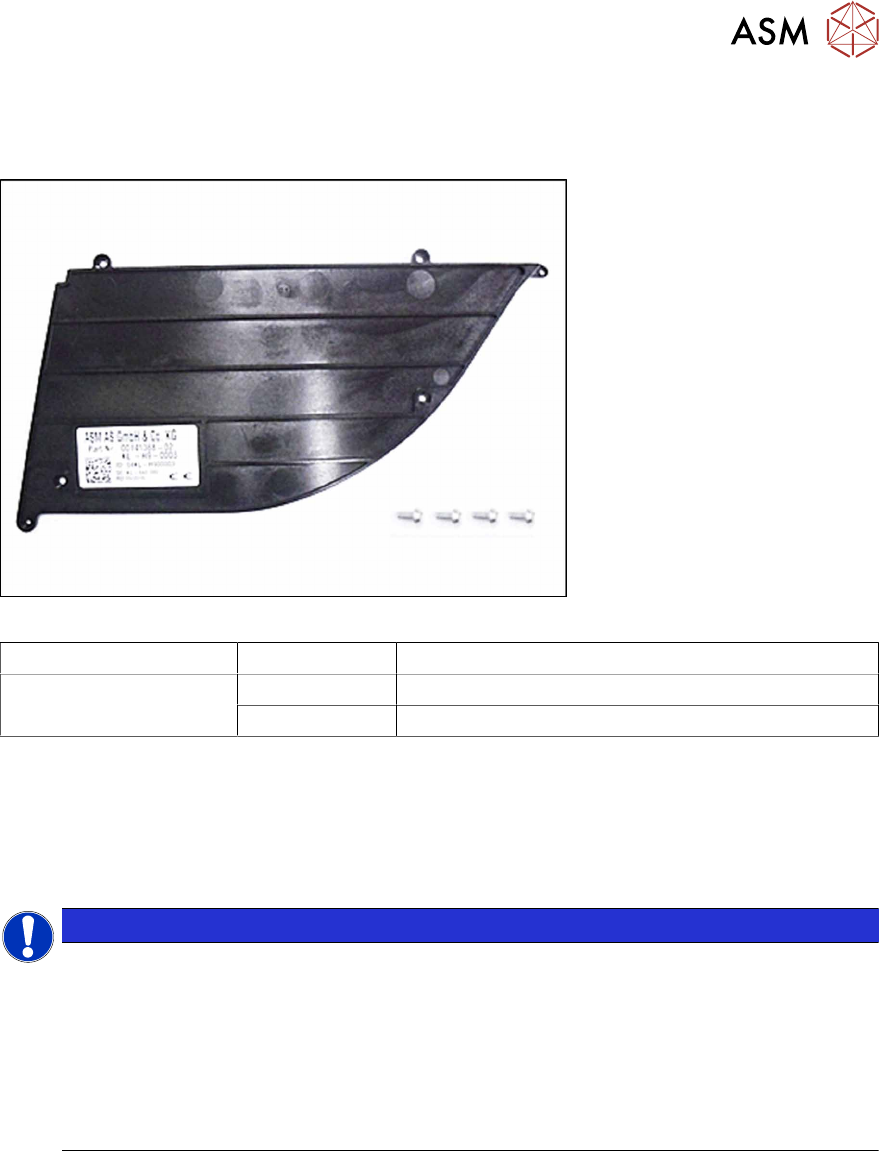
Fig.18: Insertion foil container X4Smart V2
Feeder module Item no. Designation
SmartFeeder 4mmX 03126541Sxx Insertion foil container X4Smart V2
03033796-xx RF-SN75-2.5 x 6-9.8
Required tools
●
Phillips screwdriver 0.9Nm
●
TORX screwdriver 0.6Nm, size T8
6.14.1 Replacing the foil container
NOTICE
Risk of confusion
The "insertion foil container X4Smart V2" has a label with details about the feeder module
(item number, serial number, barcode,…).
When replacing the insertion foil container, you need to create a new label and attach it to
the feeder module, so that the feeder module can be clearly identified again after the re-
placement.
For a description of how to create new labels, see section 2.5 "Creating new labels for
feeder modules" [}17].
► Carefully place the feeder module with the left side down on a stable, level and clean surface.
► Remove the right side cover (see 6.3.3 "Removing the Right Side Cover" [}32]).
6 Repairs to SmartFeeder 4 mm X
6.15 Handle with control panel
70 Service Manual SIPLACE SmartFeeder 4 - 104 mm X 11/2017
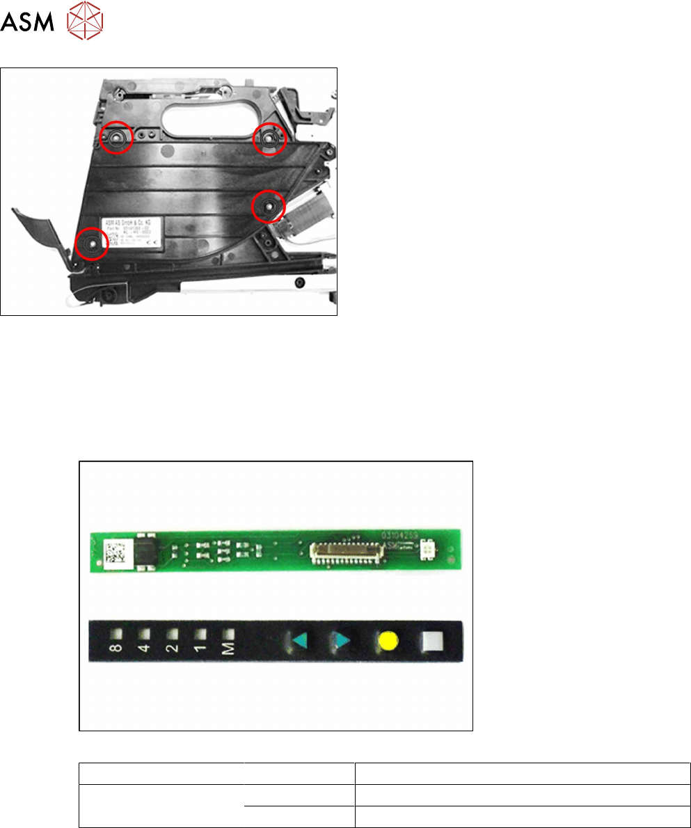
► Remove the 4 screws marked in the diagram.
Use a size 8 TORX screwdriver for this.
► Carefully remove the insertion foil container.
► Clean the foil container thoroughly and remove
all foil and adhesive residues.
► Insert the insertion foil container again.
► Fix the foil container with the 4 screws marked in
the diagram. Use a size 8 (0.6 Nm) TORX screw-
driver for this.
► Fit the right side cover (see 6.3.4 "Fitting the Right Side Cover" [}33]).
6.15 Handle with control panel
6.15.1 Control Panel Assembly
Required spare part
Fig.19: Board assy. control panel (top), control panel assy. (bottom)
Feeder module Item no. Designation
SmartFeeder 4mm X 03104269-xx Board assy. control panel X8Smart
03102428 -xx Control panel assy. X8Smart
Required tools
●
Phillips screwdriver 0.9Nm
●
TORX screwdriver size T8, 0.6Nm
●
Tweezers or small screwdriver
6 Repairs to SmartFeeder 4 mm X
6.15 Handle with control panel
Service Manual SIPLACE SmartFeeder 4 - 104 mm X 11/2017 71
6.15.1.1 Removing the Control Panel and Board
► Carefully place the feeder module with the right
side down on a stable, level and clean surface.
► Remove the left side cover (see 6.3.1 "Removing
the Left Side Cover" [}31]).
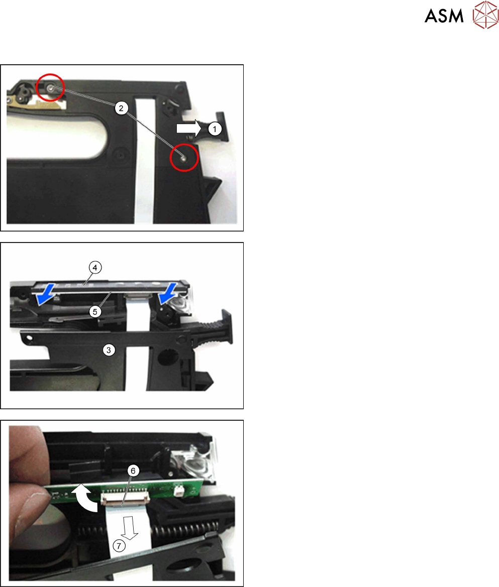
► Loosen the lock(1) in the position "unlocked".
► Open the two marked TORX screws(2), with
which the cap on the foil stuffing unit is fixed.
► Carefully lift the cap on the foil stuffing unit(3) a
little from the base of the feeder module. Make
sure that the flat ribbon cable is still fastened to
the control panel board.
► Pull the control panel(4) out of the guidance, to-
gether with the board(5).
► Open the bracket on the flat ribbon cable connec-
tion(6) at the board.
► Pull the flat ribbon cable(7) out of the flat ribbon
cable connection.
► Pull the flat ribbon cable out of the foil stuffing
unit cap.