Service Manual SIPLACE SmartFeeder.pdf - 第121页
7 Repairs to SmartFeeder 8 mm X / Xi 7.6 Splice sensor Service Manual SIPLACE SmartFeeder 4 - 8 mm X / Xi SIPLACE SmartFeeder 2 x 8 mm X / Xi 11/2020 121 ► Push the splice sensor together with the filler piece in the dir…
7 Repairs to SmartFeeder 8 mm X / Xi
7.6 Splice sensor
120 Service Manual SIPLACE SmartFeeder 4 - 8 mm X / Xi SIPLACE SmartFeeder 2 x 8 mm X / Xi 11/2020
7.6.2.2 Fitting the splice sensor filling piece
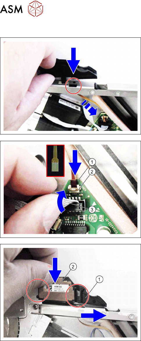
► Push the sensor cable through the recess in the
"top stiffener".
► Fit the filler piece into the recess in the "top
stiffener", as shown.
► Push the sensor cable(1) as far as the stop into
the connection shown in the diagram X301(2)
.
Make sure that the contacts are on the underside
of the cable and that the brown side of the cable
can be seen on the top.
► Lock the connection.
► Press the motor cable(3) carefully up again and
over the connection X301.
► Push the filling piece(1) to the right.
► Insert the splice sensor(2).
Make sure that the 2 fixing pins are pointing to
the left and the 3 contact pins are pointing to the
right, towards the filler piece, during the insertion.
7 Repairs to SmartFeeder 8 mm X / Xi
7.6 Splice sensor
Service Manual SIPLACE SmartFeeder 4 - 8 mm X / Xi SIPLACE SmartFeeder 2 x 8 mm X / Xi 11/2020 121
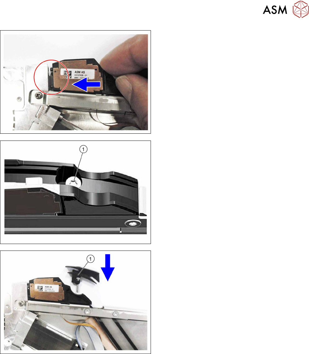
► Push the splice sensor together with the filler
piece in the direction of the arrow, as far as the
end stop on the left, so that the fixing pins of the
splice sensors are completely inserted into the
holes.
For feeder module without sensor insertion tunnel:
► Fix the filler piece with the TORK screw as
marked in the diagram RF-SN65-2.5x12(1)
.
► Fit the left side cover (see 7.3.2 "Fitting the left
side cover" [}102]).
For feeder module with sensor insertion tunnel:
► Insert the sensor insertion tunnel and the TORX
screw RF‑SN65‑2.5x12(1)
from above, as shown
in the diagram.
► Fasten the filler piece and the sensor insertion
tunnel with the TORX screw RF‑SN65‑2.5x12.
► Fit the left side cover (see 7.3.2 "Fitting the left
side cover" [}102]).
7 Repairs to SmartFeeder 8 mm X / Xi
7.6 Splice sensor
122 Service Manual SIPLACE SmartFeeder 4 - 8 mm X / Xi SIPLACE SmartFeeder 2 x 8 mm X / Xi 11/2020
7.6.3 Performing a function test
Prerequisite: to test the splice sensor, you need a test tape i.e. a piece of tape with a splice rivet
pressed onto it.
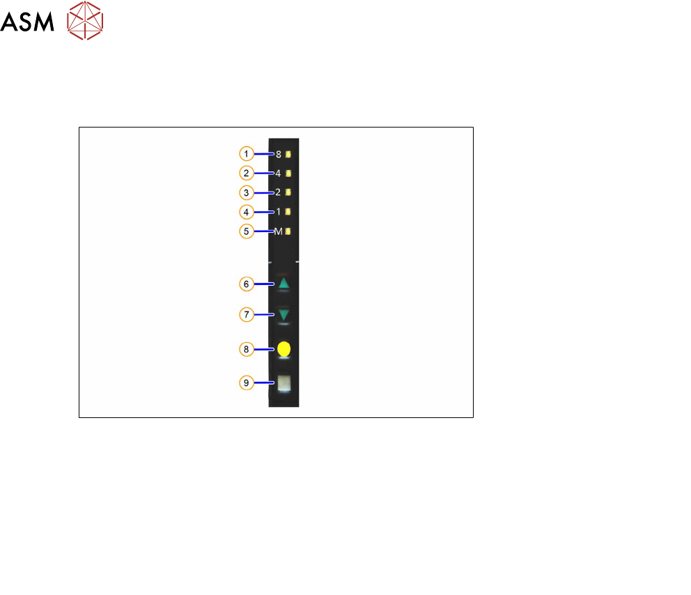
Fig.36: Control panel
1. LED 8 – 8mm pitch
(active only on SmartFeeder 8mmX)
6. FORWARDS button
2. LED 4 – 4mm pitch 7. BACKWARDS button
3. LED 2 – 2mm pitch 8. FOIL button
4. LED 1 – 1mm pitch 9. SET button
5. LED M – menu
Shines when an operator menu is active
► Place the feeder module on a single slot EDIF or on a changeover table for X feeders which is
connected to a placement machine.
► Press and hold the gray SET button on the control panel(9) until the function test is enabled.
► Press the yellow FOIL button four times briefly(8).
After the first press of the FOIL button, the LEDM will switch on.
After the second press, LED1 will also be switched on.
After the third press, LED2 will also be switched on.
After the fourth press, LED 4 will also be switched on.
The menu for the splice sensor function test has now been selected.
► Release the gray SET button, the function test has now been enabled.
► Move the test tape with the splice rivet pressed onto it up to the sensor.
If the splice sensor recognizes the splice rivet, LED 8 will shine.
If LED 8 stays off, this means that the splice rivet was not recognized. Check whether the splice
sensor was fitted properly.
If the sensor is then not recognized, check whether the flat ribbon cable for the splice sensor has
been correctly fastened (see section 7.16.2
"Fitting the control board" [}159]).
If the sensor is still not recognized, this indicates that it is probably defective and needs replacing.
► To end the test mode, press any button on the control panel. The test mode will also be ended
automatically after 1 minute.
After ending the test mode, the control panel will show the pitch currently set.