Service Manual SIPLACE SmartFeeder.pdf - 第194页
8 Repairs to SmartFeeder 2x8 mm X / Xi 8.7 Splice sensor / dummy 194 Service Manual SIPLACE SmartFeeder 4 - 8 mm X / Xi SIPLACE SmartFeeder 2 x 8 mm X / Xi 11/2020 ► Push the dummy sensor approx. 2 mm horizont- ally to t…
8 Repairs to SmartFeeder 2x8 mm X / Xi
8.7 Splice sensor / dummy
Service Manual SIPLACE SmartFeeder 4 - 8 mm X / Xi SIPLACE SmartFeeder 2 x 8 mm X / Xi 11/2020 193
8.7 Splice sensor / dummy
NOTICE
A dummy splice sensor or two splice sensors
The feeder module must always be fitted with either one dummy splice sensor or two splice
sensors.
To fasten the splice sensors, you need 2 screws: the dummy sensor only needs one.
CAUTION
Electrostatic charge
When removing and fitting the splice sensor, observe the currently applicable ESD
guidelines.
Spare part required
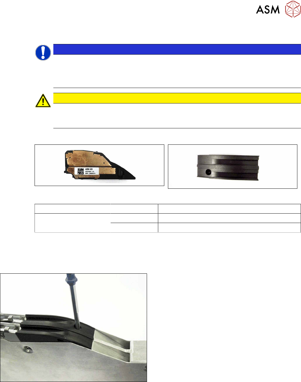
Splice sensor X2x8 Dummy splice sensor X2x8
Feeder module Item no. Designation
SmartFeeder 2x8mmX
SmartFeeder 2x8 mm Xi
03072661-xx Splice sensor X2x8
03072924-xx Dummy splice sensor X2x8
Tools required
●
Phillips screwdriver
8.7.1 Removing the Dummy Splice Sensor
► Place the feeder module down on a stable sur-
face e.g. a single slot EDIF or place the feeder
module on a level and clean surface.
► Loosen the screw fastening the dummy sensor.
Use a Phillips screwdriver for this.
8 Repairs to SmartFeeder 2x8 mm X / Xi
8.7 Splice sensor / dummy
194 Service Manual SIPLACE SmartFeeder 4 - 8 mm X / Xi SIPLACE SmartFeeder 2 x 8 mm X / Xi 11/2020
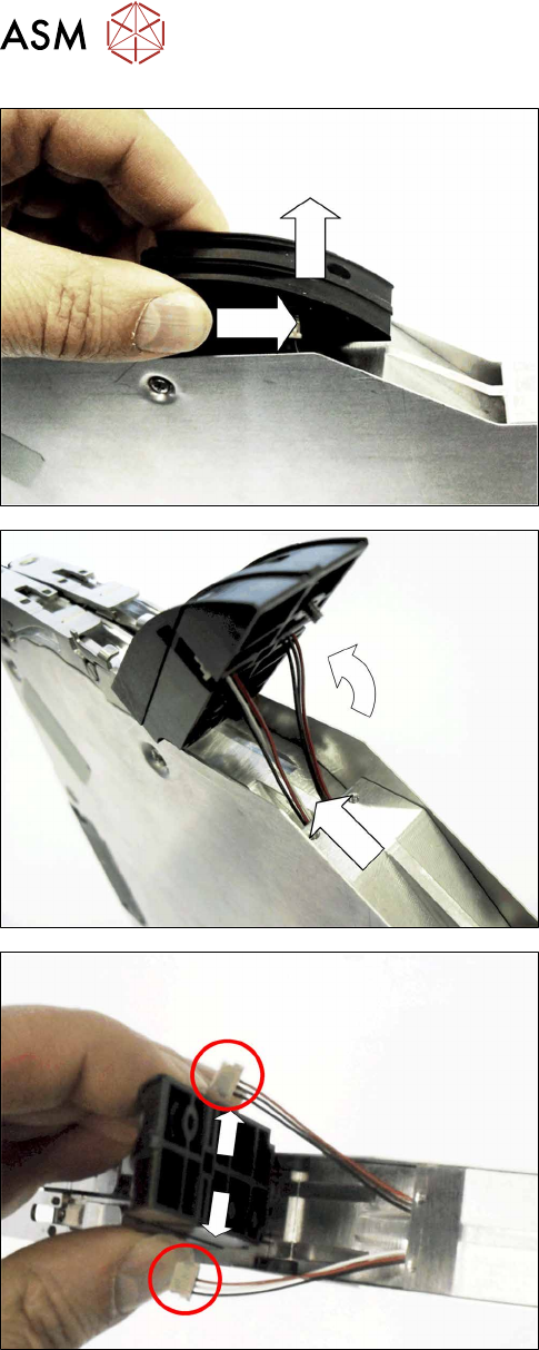
► Push the dummy sensor approx. 2 mm horizont-
ally to the right.
► Carefully lift the dummy sensor.
Make sure that the two connection lines inserted
into the dummy sensor are not damaged.
► Carefully swing the dummy sensor upwards.
► Pull the cable about 4 cm out of the base unit of
the feeder module.
► Push the connectors of the two cables out to
each side, out of the dummy sensor guidance.
► Remove the dummy sensor.
8 Repairs to SmartFeeder 2x8 mm X / Xi
8.7 Splice sensor / dummy
Service Manual SIPLACE SmartFeeder 4 - 8 mm X / Xi SIPLACE SmartFeeder 2 x 8 mm X / Xi 11/2020 195
8.7.2 Fitting the splice sensor
NOTICE
Always fit both splice sensors.
If you want to use splice sensors for the feeder module, both lanes need to be supplied with
splice sensors.
When you connect the splice sensors, make sure that you use the right cable for the lane in
each case:
- The cable for the splice sensor on the left lane has the colors red, white and black.
- The cable for the splice sensor on the right lane has the colors red, brown and black.
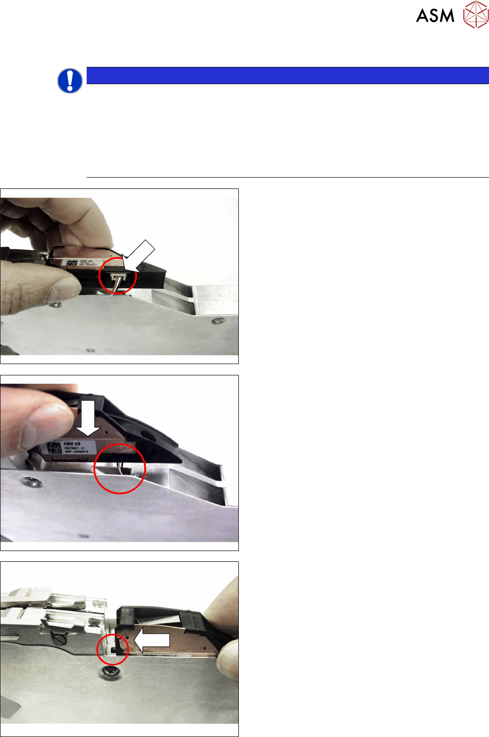
► Pull the sensor cable for that lane out of the cable
duct.
► Plug the connector for the sensor cable into the
connection on the splice sensor.
► Carefully guide the sensor cable back into the
cable duct.
► Place the splice sensor onto the lane.
Make sure that you do not pinch the cable but
that it is fed into the cable duct properly.
► Push the splice sensorin the direction of the ar-
row, as far as the stop, towards the tape duct.
Make sure that the nib at the front of the splice
sensor is completely inserted into the tape duct.