Service Manual SIPLACE SmartFeeder.pdf - 第188页
8 Repairs to SmartFeeder 2x8 mm X / Xi 8.6 Sealing elements on pin wheel 188 Service Manual SIPLACE SmartFeeder 4 - 8 mm X / Xi SIPLACE SmartFeeder 2 x 8 mm X / Xi 11/2020 ► Remove the outer panel (1) from the right foi…
8 Repairs to SmartFeeder 2x8 mm X / Xi
8.6 Sealing elements on pin wheel
Service Manual SIPLACE SmartFeeder 4 - 8 mm X / Xi SIPLACE SmartFeeder 2 x 8 mm X / Xi 11/2020 187
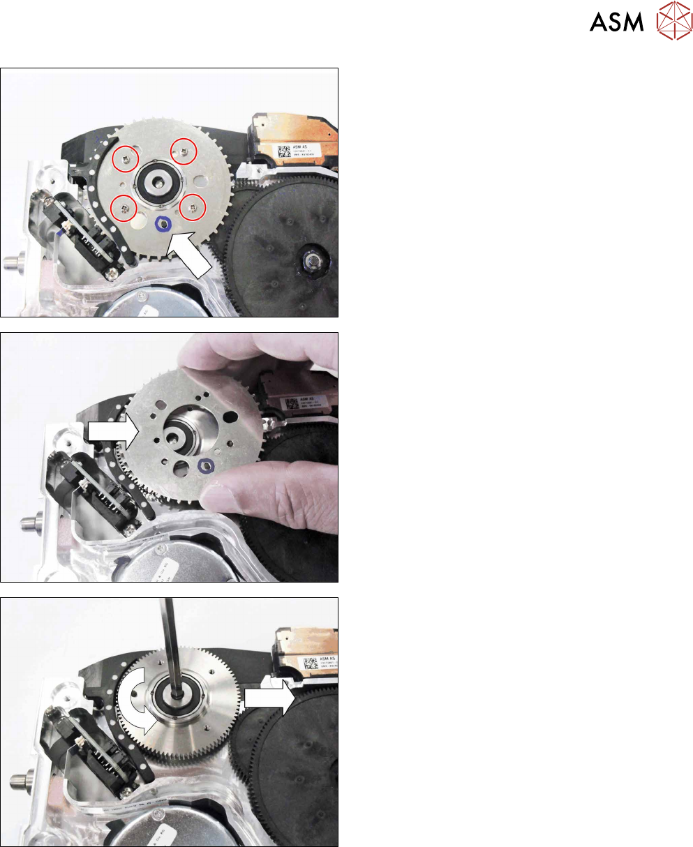
The pin crown on the left track is fastened to the pin
wheel base below it with 4 screws.
The positioning of the pin crown to the pin wheel base
is set with the help of a pin.
► To make subsequent assembly easier, mark the
hole in which the pin is currently located.
► Remove the 4 screws marked.
► Carefully lift off the pin crown.
► Pull the pin crown to the right and out of the seal-
ing elements.
► Use an Allen screwdriver, size 4, to loosen the
pin wheel base bearing.
► Remove the pin wheel base.
► Remove the right side cover (see section 8.3.3
"Removing the Right Side Cover" [}175]).
8 Repairs to SmartFeeder 2x8 mm X / Xi
8.6 Sealing elements on pin wheel
188 Service Manual SIPLACE SmartFeeder 4 - 8 mm X / Xi SIPLACE SmartFeeder 2 x 8 mm X / Xi 11/2020
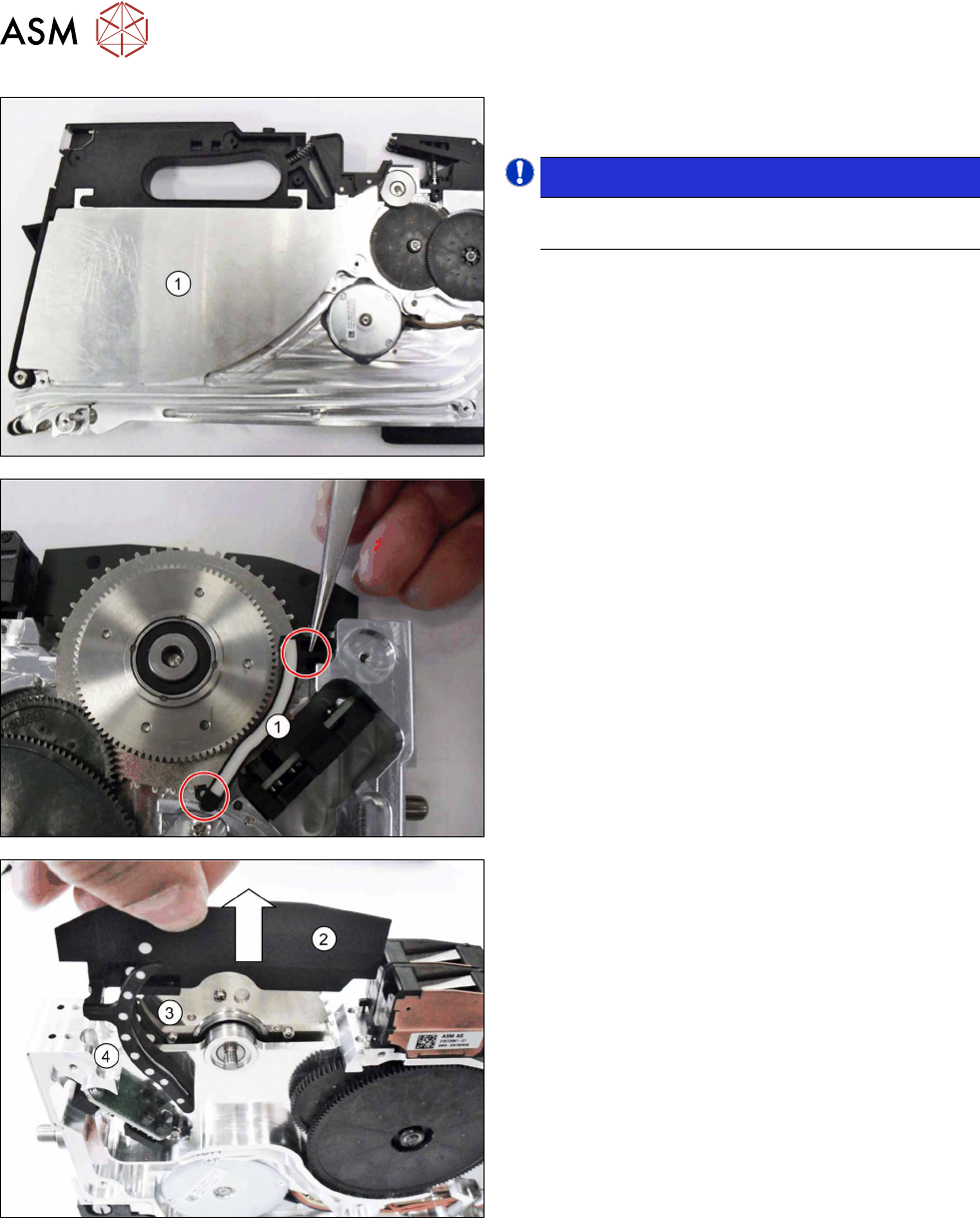
► Remove the outer panel(1) from the right foil
container.
NOTICE!
Take note: the outer panel is only placed on top
and could fall out.
.
The right sealing element(1) is attached to the middle
sealing element with two pins.
► Use tweezers to pull the two marked pin on the
right sealing element(1)
out of the middle sealing
element.
► Pull the remaining sealing elements(2), (3); and
(4)
up and out of the feeder module.
► In the area now accessible, remove all tape and
component residues.
8 Repairs to SmartFeeder 2x8 mm X / Xi
8.6 Sealing elements on pin wheel
Service Manual SIPLACE SmartFeeder 4 - 8 mm X / Xi SIPLACE SmartFeeder 2 x 8 mm X / Xi 11/2020 189
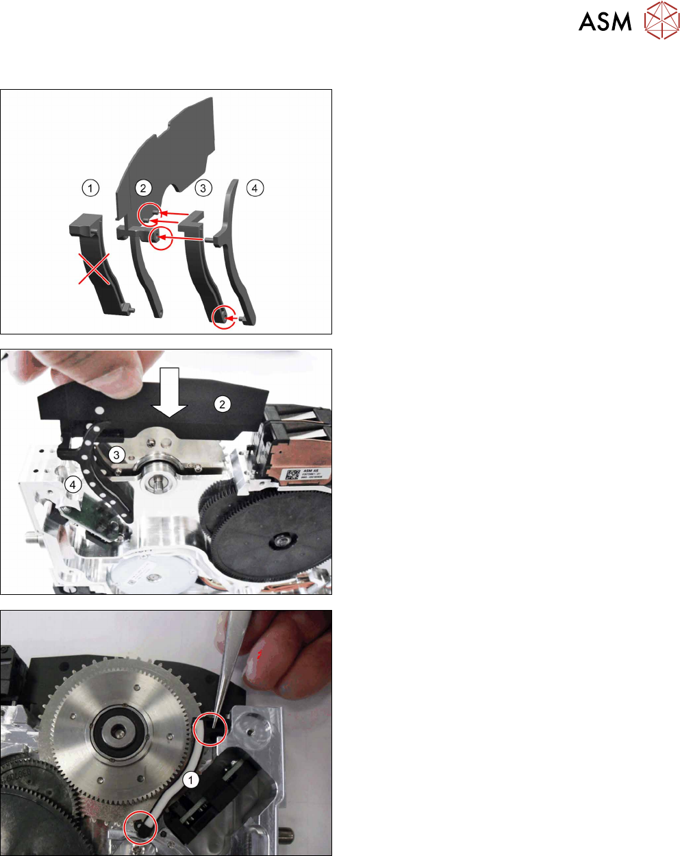
8.6.2 Fitting the sealing elements onto the pin wheel
► Fit the left middle sealing element(3) onto the
two marked pins belonging to the middle sealing
element(2)
.
► Fit the top pin for the left sealing element(4) into
the hole marked for the middle sealing ele-
ment(2)
.
► Fit the bottom pin for the left sealing element(4)
into the hole marked for the left middle sealing
element(3)
.
► The right sealing element(1) is connected later to
the middle sealing element(2)
.
► Insert the preassembled sealing elements(2), (3)
and (4) into the tape drive from above.
► Fit the two pins for the right sealing element(1)
onto the holes in the middle sealing element.
► Press the two pins into the middle sealing ele-
ment, as far as the stopper.