Service Manual SIPLACE SmartFeeder.pdf - 第200页
8 Repairs to SmartFeeder 2x8 mm X / Xi 8.7 Splice sensor / dummy 200 Service Manual SIPLACE SmartFeeder 4 - 8 mm X / Xi SIPLACE SmartFeeder 2 x 8 mm X / Xi 11/2020 8.7.5 Cable splice sensor Spare part required Fig.61: C…
8 Repairs to SmartFeeder 2x8 mm X / Xi
8.7 Splice sensor / dummy
Service Manual SIPLACE SmartFeeder 4 - 8 mm X / Xi SIPLACE SmartFeeder 2 x 8 mm X / Xi 11/2020 199
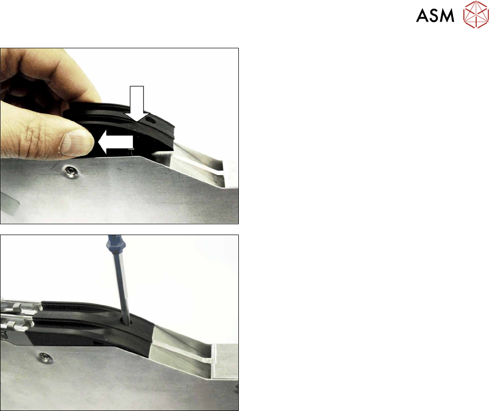
► Lower the dummy sensor completely down.
► Push the dummy sensorforwards, in the direction
of the arrow, as far as the stop.
► Fasten the dummy sensor with a screw (M2,
5x6).
Use a Phillips screwdriver for this.
8 Repairs to SmartFeeder 2x8 mm X / Xi
8.7 Splice sensor / dummy
200 Service Manual SIPLACE SmartFeeder 4 - 8 mm X / Xi SIPLACE SmartFeeder 2 x 8 mm X / Xi 11/2020
8.7.5 Cable splice sensor
Spare part required
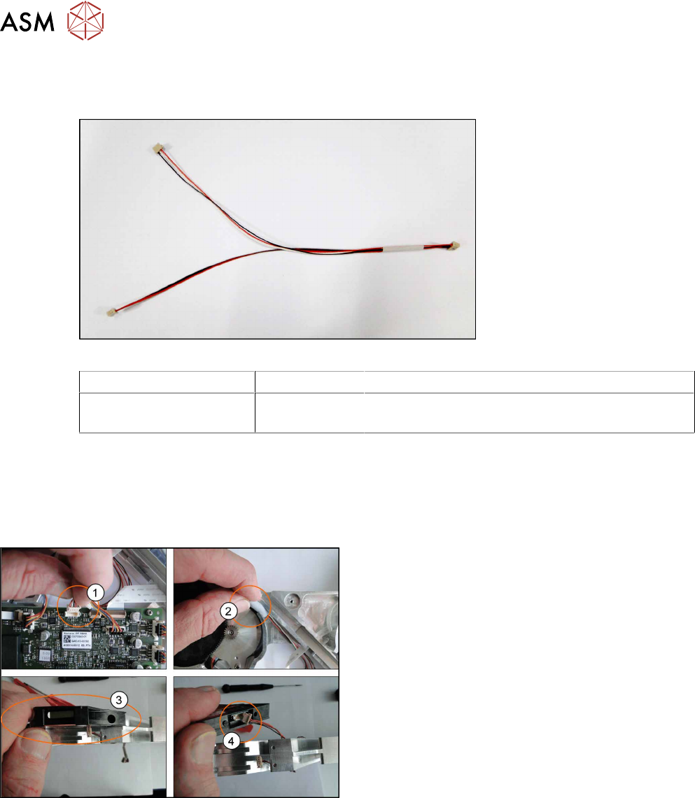
Fig.61: Cable splice sensor
Feeder module Item no. Designation
SmartFeeder 2x8 mm X
SmartFeeder 2x8 mm Xi
03063593-xx Cable for splice sensor X2x8
Tools required
●
Phillips screwdriver
●
TORX screwdriver size T8
8.7.5.1 Removing the Cable Splice Sensor
► Place the feeder on a stable, level and clean sur-
face.
► Remove the left and right side covers. (See 8.3.1
"Removing the Left Side Cover" [}174], 8.3.3
"Removing the Right Side Cover" [}175])
► Disconnect the connector from the main
board(1)
.
► Remove the seal band left and right(2).
► Remove the M2.5x6 screw from splice sensor(3)
and disconnect the cables(4).
8 Repairs to SmartFeeder 2x8 mm X / Xi
8.7 Splice sensor / dummy
Service Manual SIPLACE SmartFeeder 4 - 8 mm X / Xi SIPLACE SmartFeeder 2 x 8 mm X / Xi 11/2020 201
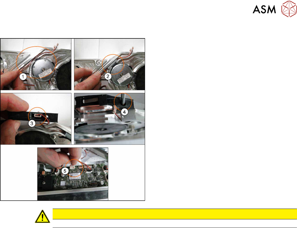
8.7.5.2 Fitting the Cable Splice Sensor
► Lay the new cables(1).
► Place the seal band left and right level with the
channel. Ensure the cables can move freely.(2)
.
► Reconnect the cables to the splice sensor(3).
► Refit the splice sensor using the M2 5x6
screw(4)
.
► Connect the connector to the main board(5).
► Fit the left and right side covers. (See 8.3.2 "Fit-
ting the Left Side Cover" [}175], 8.3.4 "Fitting the
Right Side Cover" [}176])
CAUTION
Ensure the cables are not trapped between housing, splice sensor and covers.