Service Manual SIPLACE SmartFeeder.pdf - 第204页
8 Repairs to SmartFeeder 2x8 mm X / Xi 8.8 Drives 204 Service Manual SIPLACE SmartFeeder 4 - 8 mm X / Xi SIPLACE SmartFeeder 2 x 8 mm X / Xi 11/2020 8.8.1.2 Fitting the hybrid stepping motor assembly NOTICE The installat…
8 Repairs to SmartFeeder 2x8 mm X / Xi
8.8 Drives
Service Manual SIPLACE SmartFeeder 4 - 8 mm X / Xi SIPLACE SmartFeeder 2 x 8 mm X / Xi 11/2020 203
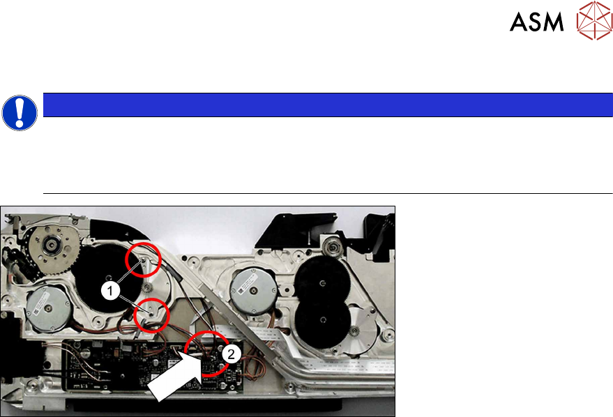
8.8.1.1 Removing the hybrid stepping motor assy.
NOTICE
The removal procedure is the same for the left and right lane.
This section describes the removal of the hybrid stepping motor on the left side (lane 1).
The removal procedure for the hybrid stepping motor on the right side (lane 2) is the same,
except that it is laterally reversed.
► Place the feeder module with the right side down on a stable, level and clean surface.
► Remove the left side cover (see 8.3.1 "Removing the Left Side Cover" [}174]).
► Remove the shifted gear tape (see 8.8.2.1 "Removing the shifted gear 1 tape left/
right" [}206]).
► Remove the two screws marked in the diagram.(1)
► Remove the plug of the motor cable from the main board.(2)
► Remove the motor and cable.
8 Repairs to SmartFeeder 2x8 mm X / Xi
8.8 Drives
204 Service Manual SIPLACE SmartFeeder 4 - 8 mm X / Xi SIPLACE SmartFeeder 2 x 8 mm X / Xi 11/2020
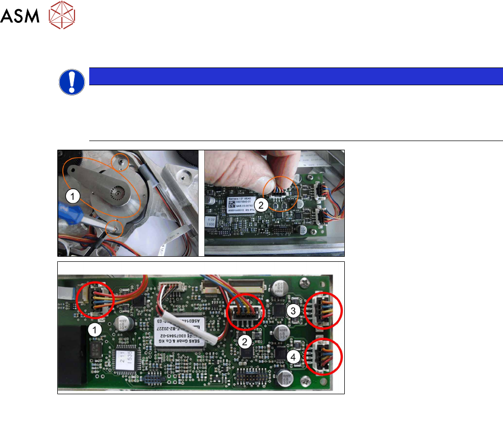
8.8.1.2 Fitting the hybrid stepping motor assembly
NOTICE
The installation procedure is the same for the left and right lane
This section describes the installation of the hybrid stepping motor on the left side (lane 1).
The installation procedure for the hybrid stepping motor on the right side (lane 2) is the
same, except that it is laterally reversed.
Fig.63: Overview of connections on the control board
1. Tape drive left lane (lane 1) 3. Foil drive left lane (lane 1)
2. Tape drive right lane (lane 2) 4. Foil drive right lane (lane 2)
► Place the hybrid stepping motor in position and run the cable through the housing.
► Fit the gauge (1) for the tape motor.
► Use the two Phillips screws marked in the diagram to fasten the motor to 0.9Nm.
► Remove the gauge.
► Plug the motor cable connector into the relevant connection on the control board e.g. for the
foil drive of the left lane (lane 1).(2)
Select the connection which matches the motor from the "Overview of connections on the
control board" shown above.
► Refit the shifted gear (see 8.8.2.2 "Fitting the shifted gear 1 left / right tape" [}206]).
► Fasten the left side covers (see 8.3.2 "Fitting the Left Side Cover" [}175])
8 Repairs to SmartFeeder 2x8 mm X / Xi
8.8 Drives
Service Manual SIPLACE SmartFeeder 4 - 8 mm X / Xi SIPLACE SmartFeeder 2 x 8 mm X / Xi 11/2020 205
8.8.2 Shifted gear for tape drive
NOTICE
Spare parts kit
Due to the potential wear of plastic toothed wheels, it is recommended that, when you find it
necessary to replace one shifted gear or toothed wheel, you also replace the other one.
For this purpose, we recommend the spare parts kit "ETP gear set tape X
2x8mm“ [03095484-xx], which contains both toothed wheels with washers and circlips.
Spare parts required
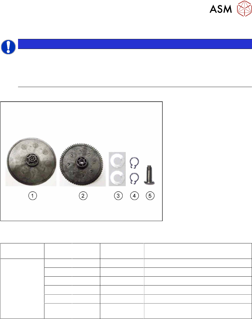
Fig.64: Spare parts kit "ETP gear set tape X 2x8mm" [03095484-xx]
The spare parts provided in the gear set are listed in the following table:
Feeder mod-
ule
Position Number Item no. Designation
SmartFeeder
2x8mmX
SmartFeeder
2x8 mm Xi
1 03095484-xx ETP drive unit tape X 2x8mm
1 1 03070908-xx Shifted gear 1 tape PA /X2x8
2 1 03070911-xx Toothed wheel 4 tape PA /X2x8
3 2 03083028-xx DIN 988-3x6x0.1-1.4310 (washer)
4 2 00305726-xx DIN 471-3x0.4-C67 (circlip)
5 1 03079902-xx Threaded axis toothed wheel 4 tape /
X2x8
In the SmartFeeder 2x8mmX, the toothed wheels for the shifted gear tape drive are fitted in differ-
ent ways.
The drive for the left lane is fitted with the "toothed wheel 4 tape PA /X2x8“ [03070911-xx] with the
"threaded axis toothed wheel 4 tape / X2x8" [03079902-xx]. The "shifted gear 1 tape PA /
X2x8" [03070908-xx], and the "toothed wheel 4 tape PA /X2x8" for the right lane are fitted with
washer and circlip.
The spare parts kit "ETP gear set tape X 2x8mm" [03095484-xx] contains all the parts in the follow-
ing table, in the quantities listed.
Tools required
●
Circlip pliers for outer rings 3-10 mm
●
Allen key 0.35Nm
●
Tweezers