Service Manual SIPLACE SmartFeeder.pdf - 第202页
8 Repairs to SmartFeeder 2x8 mm X / Xi 8.8 Drives 202 Service Manual SIPLACE SmartFeeder 4 - 8 mm X / Xi SIPLACE SmartFeeder 2 x 8 mm X / Xi 11/2020 8.8 Drives 8.8.1 Hybrid stepping motor assembly left / right Spare part…
8 Repairs to SmartFeeder 2x8 mm X / Xi
8.7 Splice sensor / dummy
Service Manual SIPLACE SmartFeeder 4 - 8 mm X / Xi SIPLACE SmartFeeder 2 x 8 mm X / Xi 11/2020 201
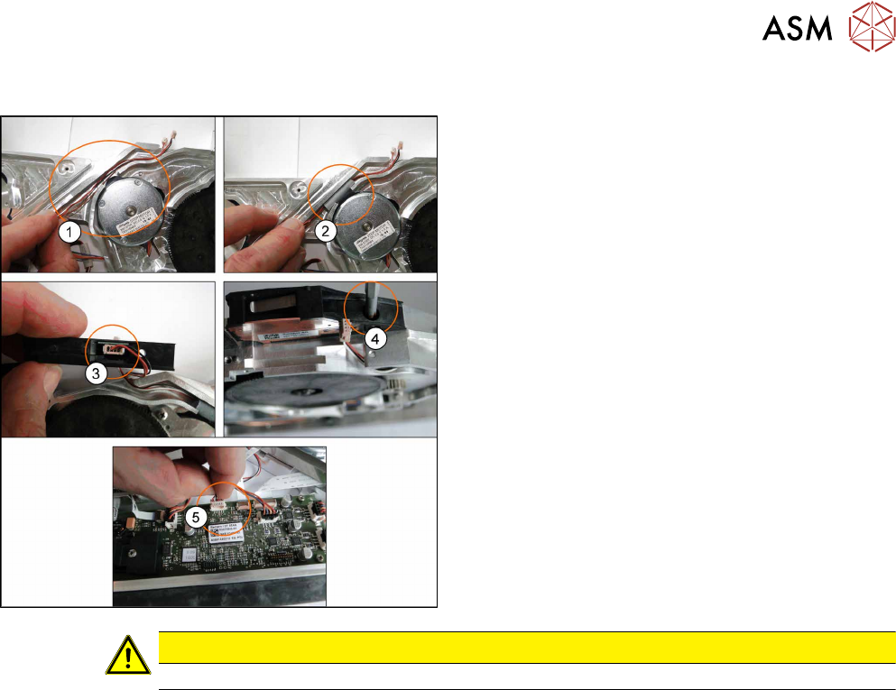
8.7.5.2 Fitting the Cable Splice Sensor
► Lay the new cables(1).
► Place the seal band left and right level with the
channel. Ensure the cables can move freely.(2)
.
► Reconnect the cables to the splice sensor(3).
► Refit the splice sensor using the M2 5x6
screw(4)
.
► Connect the connector to the main board(5).
► Fit the left and right side covers. (See 8.3.2 "Fit-
ting the Left Side Cover" [}175], 8.3.4 "Fitting the
Right Side Cover" [}176])
CAUTION
Ensure the cables are not trapped between housing, splice sensor and covers.
8 Repairs to SmartFeeder 2x8 mm X / Xi
8.8 Drives
202 Service Manual SIPLACE SmartFeeder 4 - 8 mm X / Xi SIPLACE SmartFeeder 2 x 8 mm X / Xi 11/2020
8.8 Drives
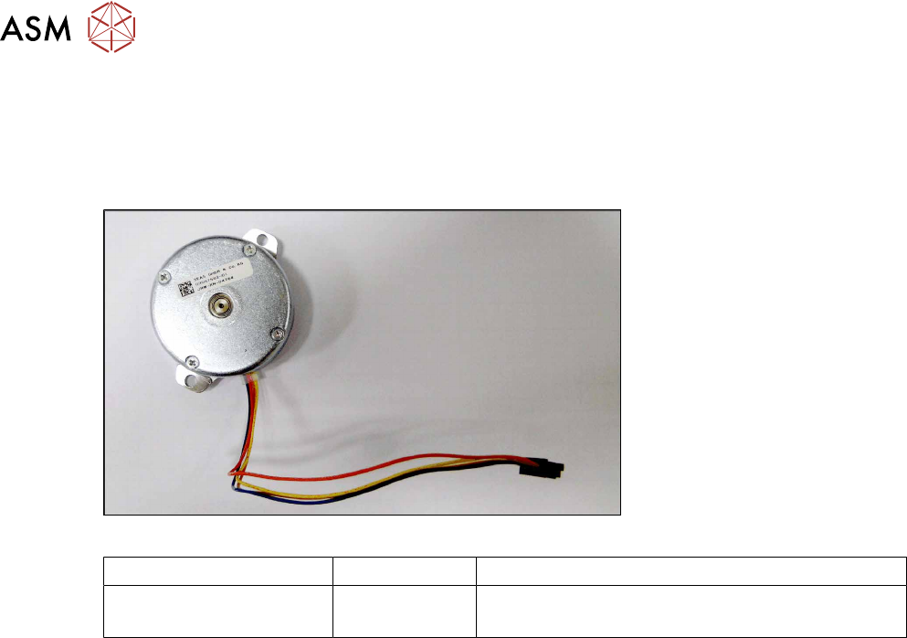
8.8.1 Hybrid stepping motor assembly left / right
Spare part required
Fig.62: Hybrid stepping motor assembly
Feeder module Item no. Designation
SmartFeeder 2x8mmX
SmartFeeder 2x8 mm Xi
03057582-xx Hybrid stepping motor assembly
Tools required
●
TORX screwdriver 0.6Nm, size T8
●
Phillips screwdriver 0.9Nm
●
Gauge for tape drive motor /X2x8, item no. 03080225-xx
●
Gauge for foil drive /X2x8, item no. 03080235-xx
8 Repairs to SmartFeeder 2x8 mm X / Xi
8.8 Drives
Service Manual SIPLACE SmartFeeder 4 - 8 mm X / Xi SIPLACE SmartFeeder 2 x 8 mm X / Xi 11/2020 203
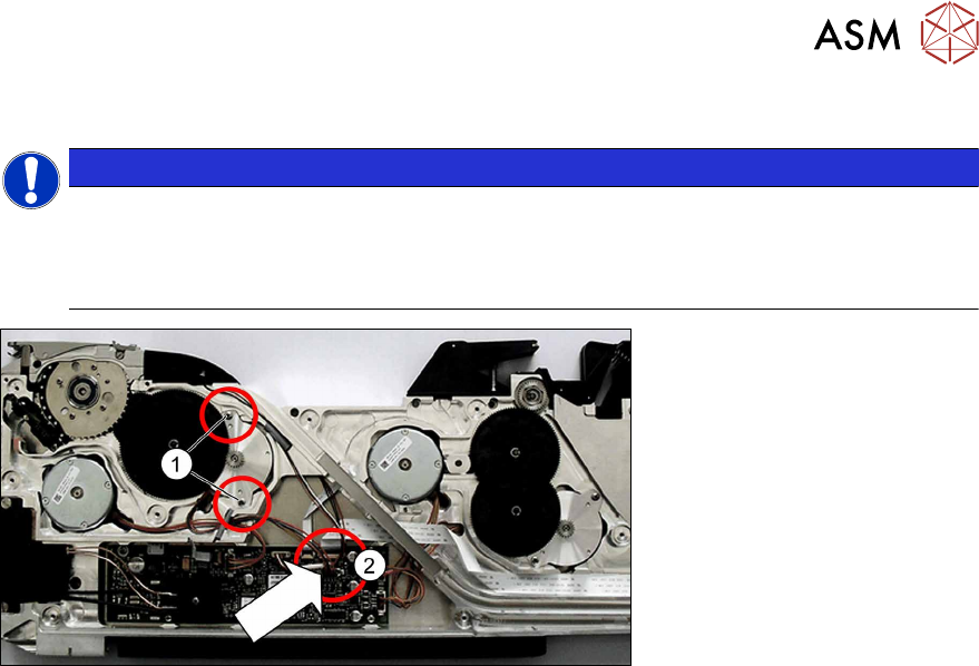
8.8.1.1 Removing the hybrid stepping motor assy.
NOTICE
The removal procedure is the same for the left and right lane.
This section describes the removal of the hybrid stepping motor on the left side (lane 1).
The removal procedure for the hybrid stepping motor on the right side (lane 2) is the same,
except that it is laterally reversed.
► Place the feeder module with the right side down on a stable, level and clean surface.
► Remove the left side cover (see 8.3.1 "Removing the Left Side Cover" [}174]).
► Remove the shifted gear tape (see 8.8.2.1 "Removing the shifted gear 1 tape left/
right" [}206]).
► Remove the two screws marked in the diagram.(1)
► Remove the plug of the motor cable from the main board.(2)
► Remove the motor and cable.