Service Manual SIPLACE SmartFeeder.pdf - 第43页
6 Repairs to SmartFeeder 4 mm X / Xi 6.6 Splice sensor Service Manual SIPLACE SmartFeeder 4 - 8 mm X / Xi SIPLACE SmartFeeder 2 x 8 mm X / Xi 11/2020 43 6.6.1 Replacing the Dummy with a Splice Sensor ► Remove the left si…
6 Repairs to SmartFeeder 4 mm X / Xi
6.6 Splice sensor
42 Service Manual SIPLACE SmartFeeder 4 - 8 mm X / Xi SIPLACE SmartFeeder 2 x 8 mm X / Xi 11/2020
6.6 Splice sensor
NOTICE
Available only for SIPLACE SmartFeeder 4mm Xi
The splice sensor can be retrofitted for "SIPLACE SmartFeeder 4mm Xi" [00141478-02]
feeder modules.
Retrofitting of a splice sensor is not possible for the old "SIPLACE SmartFeeder 4mm
X" [00141368-xx] feeder modules!
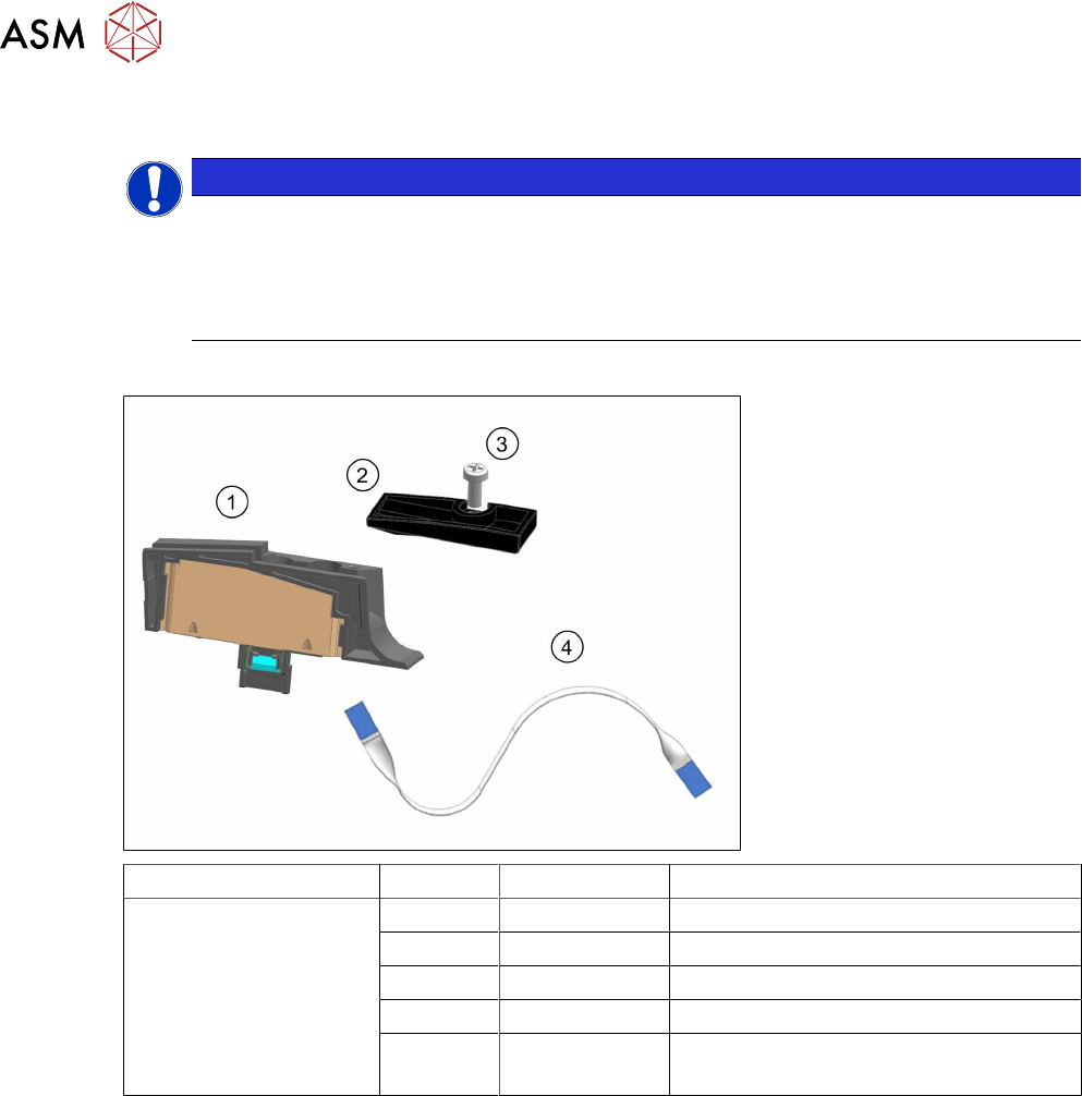
Spare parts required
Feeder module Position Item no. Designation
SmartFeeder 4 mm Xi 03160408Sxx Splice sensor X4Smart assy.
1 03165059-xx Splice sensor X4Smart
2 03160301-xx Cover on splice sensor X4Smart
3 00328542-01 SN 213307-H-M2.5 x 6-A2
(4) 03164295-xx Flat flex cable, splice sensor X4Smart
(already fitted in the feeder module)
Tools required
●
Phillips screwdriver
●
Allen key, size 3

6 Repairs to SmartFeeder 4 mm X / Xi
6.6 Splice sensor
Service Manual SIPLACE SmartFeeder 4 - 8 mm X / Xi SIPLACE SmartFeeder 2 x 8 mm X / Xi 11/2020 43
6.6.1 Replacing the Dummy with a Splice Sensor
► Remove the left side cover (see 6.3.1 "Removing the
Left Side Cover" [}30]).
► Place the feeder module in a stable, upright position.
► Remove the screw shown in the diagram.(1)
Use an Allen key, size 3 for this.
► Pull the dummy up and out of the reinforcement.(2)
► Place the flat ribbon cable into the feeder module, as
shown.
► Insert the one end of the flat ribbon cable as far as the
end stop into the top connection on the board.
Make sure that the cable contacts are on the under-
side and that the blue side of the cable can be seen
from the top (1)
► Lock the connection on the board.
► Thread the other end of the flat ribbon cable through
the opening in the reinforcement and upwards.(2)
► Insert the flat ribbon cable as far as the end stop into
the connection on the splice sensor.
Make sure that the contacts are on the underside of
the cable and that the blue side of the cable can be
seen from the top.
► Lock the connection on the splice sensor.
► Place the splice sensor on to the reinforcement, as
shown.(1)
► Fasten the splice sensor with the "REMFORM RF-
SN85-2.5 x 7.5-9.8" screw [03044543-01].(2)
Use an Allen key, size 3 for this.
► Fit the "Splice sensor cover X4Smart" [03160301-xx]
assembly onto the splice sensor.(3)
► Fix the assembly into place with the "SN 213307-H-
M2.5 x 6-A2" screw [00328542-01].(4)
Use a Phillips screwdriver, 0.6 Nm, for this.
► Fit the left side cover (see 6.3.2 "Fitting the Left Side
Cover" [}30]).
6 Repairs to SmartFeeder 4 mm X / Xi
6.6 Splice sensor
44 Service Manual SIPLACE SmartFeeder 4 - 8 mm X / Xi SIPLACE SmartFeeder 2 x 8 mm X / Xi 11/2020
6.6.2 Performing a function test
Prerequisite: to test the splice sensor, you need a test tape i.e. a piece of tape with a splice rivet
pressed onto it.
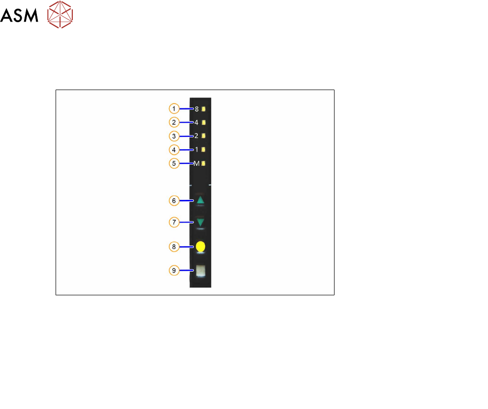
Fig.8: Control panel
1. LED 8 – 8mm pitch 6. FORWARDS button
2. LED 4 – 4mm pitch 7. BACKWARDS button
3. LED 2 – 2mm pitch 8. FOIL button
4. LED 1 – 1mm pitch 9. SET button
5. LED M – menu
Shines when an operator menu is active
► Place the feeder module on a single slot EDIF or on a changeover table for X feeders which is
connected to a placement machine.
► Press and hold the gray SET button on the control panel(9) until the function test is enabled.
► Press the yellow FOIL button four times briefly(8).
After the first press of the FOIL button, the LEDM will switch on.
After the second press, LED1 will also be switched on.
After the third press, LED2 will also be switched on.
After the fourth press, LED 4 will also be switched on.
The menu for the splice sensor function test has now been selected.
► Release the gray SET button, the function test has now been enabled.
► Move the test tape with the splice rivet pressed onto it up to the sensor.
If the splice sensor recognizes the splice rivet, LED 8 will shine.
If LED 8 stays off, this means that the splice rivet was not recognized. Check whether the splice
sensor was fitted properly.
If the sensor is then not recognized, check whether the flat ribbon cable for the splice sensor has
been correctly fastened (see section 6.16.2
"Fitting the control board" [}83]).
If the sensor is still not recognized, this indicates that it is probably defective and needs replacing.
► To end the test mode, press any button on the control panel. The test mode will also be ended
automatically after 1 minute.
After ending the test mode, the control panel will show the pitch currently set.