Service Manual SIPLACE SmartFeeder.pdf - 第42页
6 Repairs to SmartFeeder 4 mm X / Xi 6.6 Splice sensor 42 Service Manual SIPLACE SmartFeeder 4 - 8 mm X / Xi SIPLACE SmartFeeder 2 x 8 mm X / Xi 11/2020 6.6 Splice sensor NOTICE Available only for SIPLACE SmartFeeder 4mm…
6 Repairs to SmartFeeder 4 mm X / Xi
6.5 Pickup window
Service Manual SIPLACE SmartFeeder 4 - 8 mm X / Xi SIPLACE SmartFeeder 2 x 8 mm X / Xi 11/2020 41
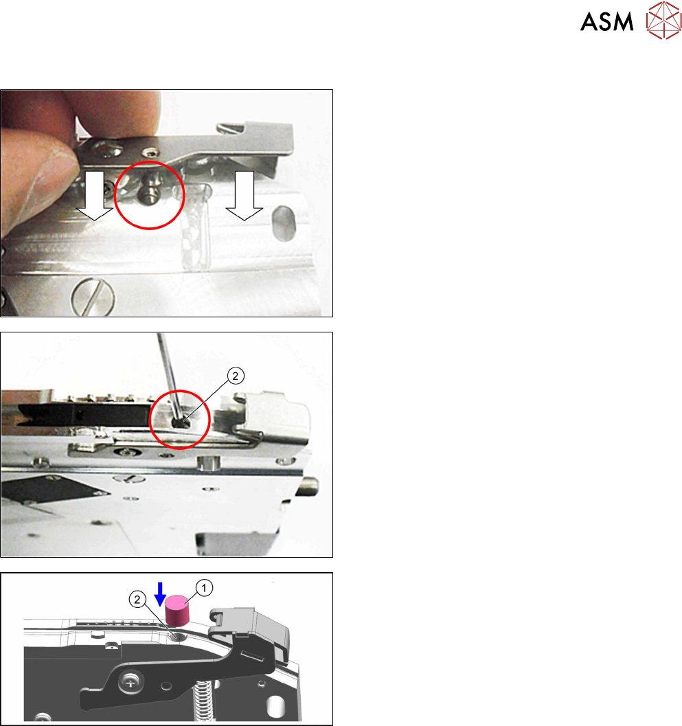
6.5.4 Fitting the actuator
► Push the actuator on the righthand side of the
feeder module into the base unit as shown.
During this, push the actuator axis into the hole
shown in the diagram.
► Fasten the actuator axis with a fitting screw(2).
Use a 1.5mm Allen key for this.
► Fit the sealing element (1) onto the fitting screw
hole (2).
► Fasten the pickup window (see 6.5.2 "Fitting the
pickup window" [}38]).
6 Repairs to SmartFeeder 4 mm X / Xi
6.6 Splice sensor
42 Service Manual SIPLACE SmartFeeder 4 - 8 mm X / Xi SIPLACE SmartFeeder 2 x 8 mm X / Xi 11/2020
6.6 Splice sensor
NOTICE
Available only for SIPLACE SmartFeeder 4mm Xi
The splice sensor can be retrofitted for "SIPLACE SmartFeeder 4mm Xi" [00141478-02]
feeder modules.
Retrofitting of a splice sensor is not possible for the old "SIPLACE SmartFeeder 4mm
X" [00141368-xx] feeder modules!
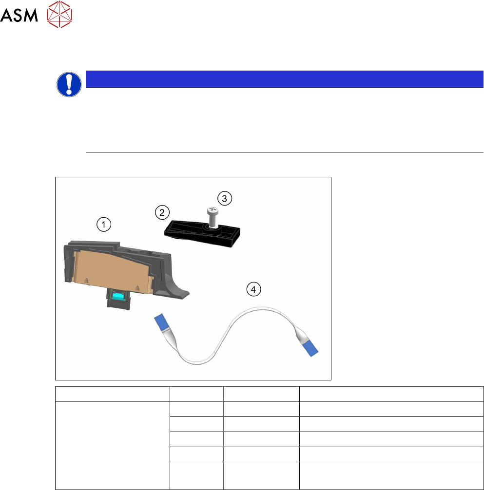
Spare parts required
Feeder module Position Item no. Designation
SmartFeeder 4 mm Xi 03160408Sxx Splice sensor X4Smart assy.
1 03165059-xx Splice sensor X4Smart
2 03160301-xx Cover on splice sensor X4Smart
3 00328542-01 SN 213307-H-M2.5 x 6-A2
(4) 03164295-xx Flat flex cable, splice sensor X4Smart
(already fitted in the feeder module)
Tools required
●
Phillips screwdriver
●
Allen key, size 3

6 Repairs to SmartFeeder 4 mm X / Xi
6.6 Splice sensor
Service Manual SIPLACE SmartFeeder 4 - 8 mm X / Xi SIPLACE SmartFeeder 2 x 8 mm X / Xi 11/2020 43
6.6.1 Replacing the Dummy with a Splice Sensor
► Remove the left side cover (see 6.3.1 "Removing the
Left Side Cover" [}30]).
► Place the feeder module in a stable, upright position.
► Remove the screw shown in the diagram.(1)
Use an Allen key, size 3 for this.
► Pull the dummy up and out of the reinforcement.(2)
► Place the flat ribbon cable into the feeder module, as
shown.
► Insert the one end of the flat ribbon cable as far as the
end stop into the top connection on the board.
Make sure that the cable contacts are on the under-
side and that the blue side of the cable can be seen
from the top (1)
► Lock the connection on the board.
► Thread the other end of the flat ribbon cable through
the opening in the reinforcement and upwards.(2)
► Insert the flat ribbon cable as far as the end stop into
the connection on the splice sensor.
Make sure that the contacts are on the underside of
the cable and that the blue side of the cable can be
seen from the top.
► Lock the connection on the splice sensor.
► Place the splice sensor on to the reinforcement, as
shown.(1)
► Fasten the splice sensor with the "REMFORM RF-
SN85-2.5 x 7.5-9.8" screw [03044543-01].(2)
Use an Allen key, size 3 for this.
► Fit the "Splice sensor cover X4Smart" [03160301-xx]
assembly onto the splice sensor.(3)
► Fix the assembly into place with the "SN 213307-H-
M2.5 x 6-A2" screw [00328542-01].(4)
Use a Phillips screwdriver, 0.6 Nm, for this.
► Fit the left side cover (see 6.3.2 "Fitting the Left Side
Cover" [}30]).