Service Manual SIPLACE SmartFeeder.pdf - 第161页
7 Repairs to SmartFeeder 8 mm X / Xi 7.16 Control board Service Manual SIPLACE SmartFeeder 4 - 8 mm X / Xi SIPLACE SmartFeeder 2 x 8 mm X / Xi 11/2020 161 7.16.3 Performing a reference run Fig.53: Control panel 1. LED 8…
7 Repairs to SmartFeeder 8 mm X / Xi
7.16 Control board
160 Service Manual SIPLACE SmartFeeder 4 - 8 mm X / Xi SIPLACE SmartFeeder 2 x 8 mm X / Xi 11/2020
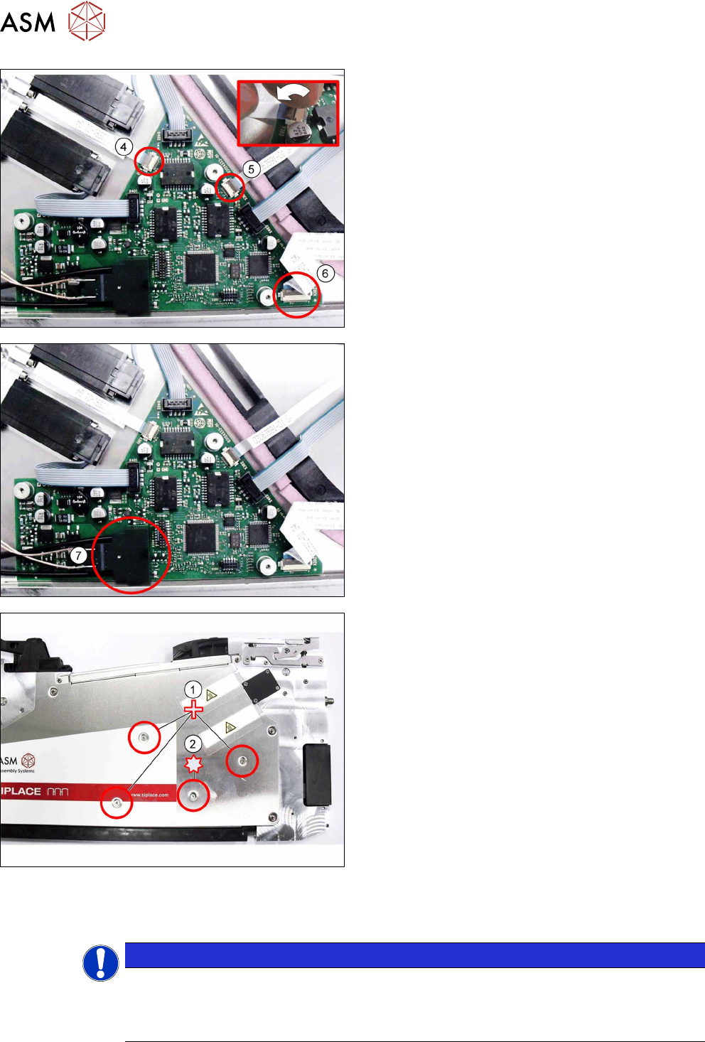
Connect the 3 flat ribbon cables(4-6) to the control
board. Proceed as follows for this:
► Push the flat ribbon cable as far as the stop into
the connection shown in the diagram.
Make sure that the contacts are on the underside
of the cable and that the blue side of the cable
can be seen on the top.
► Lock the connection (see the diagram, top right).
► Insert the EDIF connector (7) into the marked
connection on the control board.
► Align the position of the control board again, us-
ing the 3 holes in the control board and the 3
holes in the side cover.
► Carefully place the feeder module with the left
side down on a stable, level and clean surface,
while holding the control board in its position.
► Fasten the control board with the 3 Phillips screws
shown in the diagram(1)
to the right side cover.
► Make sure that the EDIF connector is correctly in-
serted onto the control board.
► Carefully fasten the EDIF connector with the TORX
screw shown in the diagram(2)
.
Use a size T8 TORX screwdriver with 0.2 Nm. for this.
► Carefully place the feeder module with the right
side down on a stable, level and clean surface.
► Fasten the left side cover (see section 7.3.2 "Fit-
ting the left side cover" [}102]).
NOTICE
Reference run
After replacing the control board, it is essential that you perform a reference run of the
feeder module! For a detailed description, refer to section7.16.3
"Performing a reference
run" [}161].
7 Repairs to SmartFeeder 8 mm X / Xi
7.16 Control board
Service Manual SIPLACE SmartFeeder 4 - 8 mm X / Xi SIPLACE SmartFeeder 2 x 8 mm X / Xi 11/2020 161
7.16.3 Performing a reference run
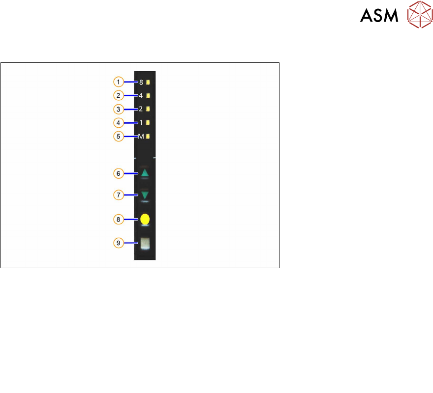
Fig.53: Control panel
1. LED 8 – 8mm pitch
(active only on SmartFeeder 8mmX)
6. FORWARDS button
2. LED 4 – 4mm pitch 7. BACKWARDS button
3. LED 2 – 2mm pitch 8. FOIL button
4. LED 1 – 1mm pitch 9. SET button
5. LED M – menu
Shines when an operator menu is active
► Place the feeder module on a single slot EDIF or on a changeover table for X feeders which is
connected to a placement machine.
► Press and hold the gray SET button(9) until the reference run is enabled.
► Press the yellow foil button three times briefly(8).
After the first press of the FOIL button, the LEDM will switch on.
After the second press, LED1 will also be switched on.
After the third press, LED2 will also be switched on.
The menu for enabling the reference run has now been selected.
► In addition to the SET button, also press the FORWARDS button(7).
LED8(1)
should now flash rapidly. If LED8 and LED4(2) flash, this indicates that there is a
feeder module error present (e.g. foil is tensioned or tape drive has an error) and the refer-
ence run can not be performed.
► Release the FORWARDS button.
The reference run will start.
► Release the SET button.
The reference run will be automatically finished. The control panel will then switch over to the
pitch display.
7 Repairs to SmartFeeder 8 mm X / Xi
7.17 Foil container
162 Service Manual SIPLACE SmartFeeder 4 - 8 mm X / Xi SIPLACE SmartFeeder 2 x 8 mm X / Xi 11/2020
7.17 Foil container
7.17.1 Foil box
Spare part required
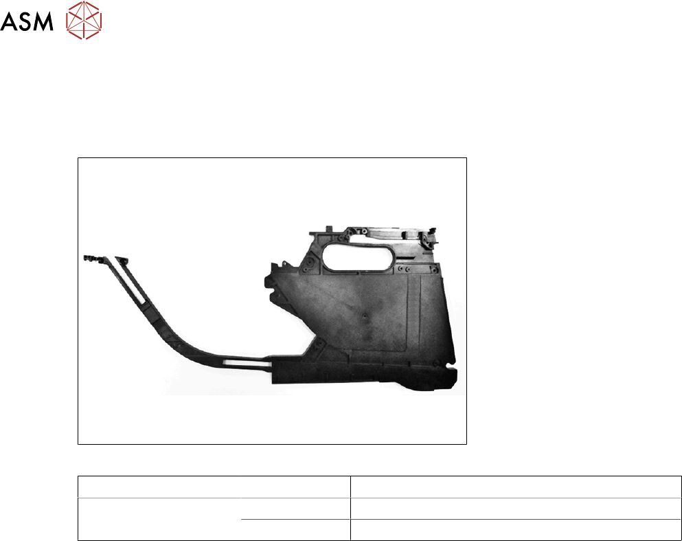
Fig.54: Foil box
Feeder module Item no. Designation
SmartFeeder 8mmX
SmartFeeder 8 mm Xi
03100963-xx Foil box with tape duct X8Smart
03100995-xx Foil box sheet for cover foil stuffing unit X8Smart
Tools required
●
Phillips screwdriver 0.9Nm
●
TORX screwdriver 0.6Nm, size T8
●
Flat-bladed screwdriver size 1
●
Tweezers