Service Manual SIPLACE SmartFeeder.pdf - 第83页
6 Repairs to SmartFeeder 4 mm X / Xi 6.16 Control board Service Manual SIPLACE SmartFeeder 4 - 8 mm X / Xi SIPLACE SmartFeeder 2 x 8 mm X / Xi 11/2020 83 6.16.2 Fitting the control board ► Carefully place the feeder modu…
6 Repairs to SmartFeeder 4 mm X / Xi
6.16 Control board
82 Service Manual SIPLACE SmartFeeder 4 - 8 mm X / Xi SIPLACE SmartFeeder 2 x 8 mm X / Xi 11/2020
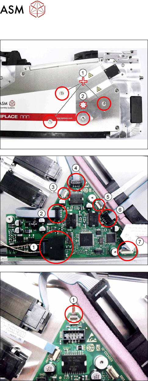
6.16.1 Removing the control board
► Carefully place the feeder module with the left
side down on a stable, level and clean surface.
► Remove the three Phillips screws marked in the
picture(1)
, which fasten the control board to the
right side cover.
► Carefully remove the TORX screw shown in the
diagram(2)
, which fastens the EDIF connector to
the control board.
Use a size 8 TORX screwdriver for this.
► Carefully place the feeder module with the right
side down on a stable, level and clean surface.
► Remove the left side cover (see section 6.3.1
"Removing the Left Side Cover" [}30]).
► Remove the EDIF connector(1).
► Loosen the 6 connections shown in the dia-
gram(2 – 7)
.
► If there is a splice sensor fitted in the feeder mod-
ule, open the connection to the splice sensor
cable.(1)
► Remove the control board.
6 Repairs to SmartFeeder 4 mm X / Xi
6.16 Control board
Service Manual SIPLACE SmartFeeder 4 - 8 mm X / Xi SIPLACE SmartFeeder 2 x 8 mm X / Xi 11/2020 83
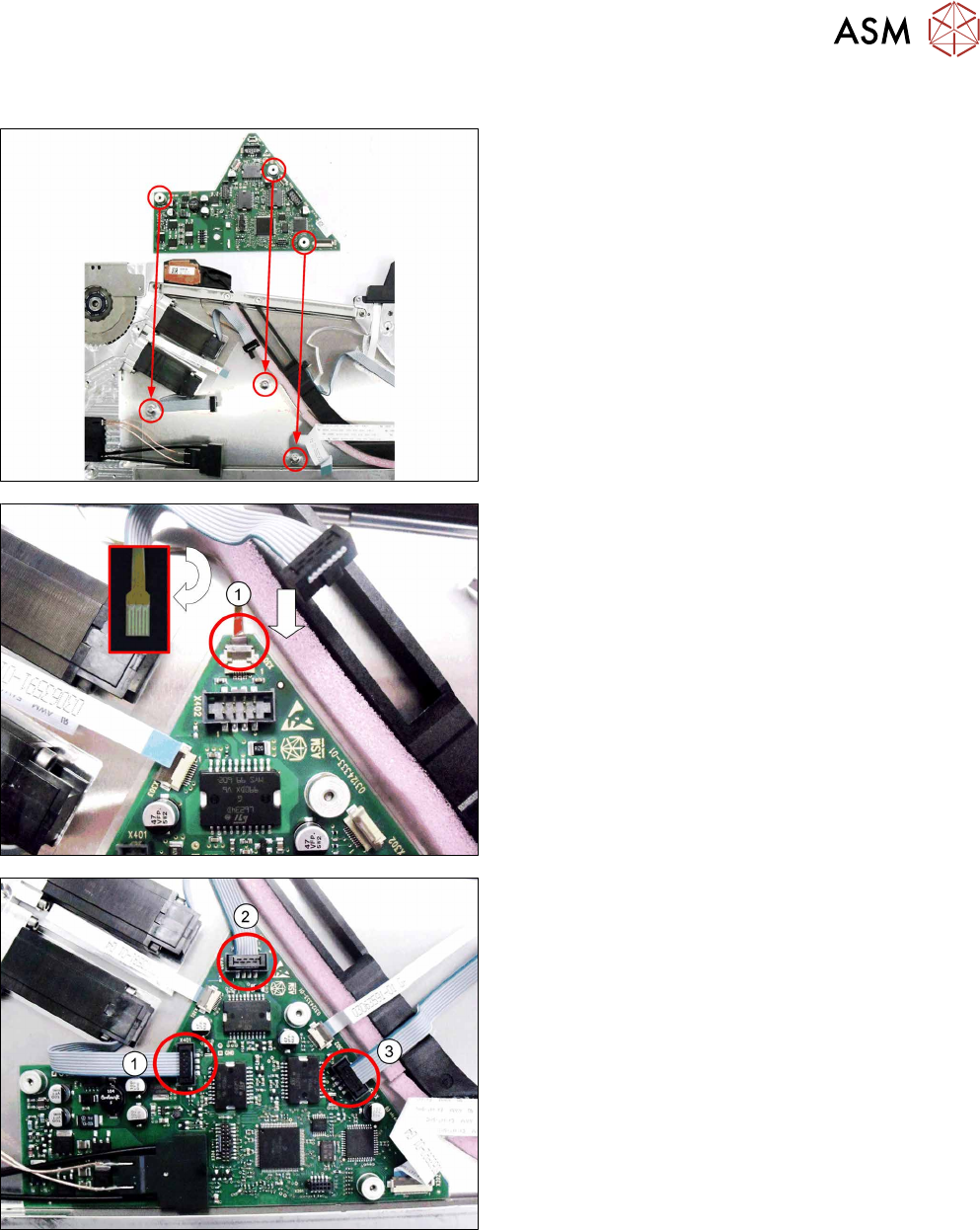
6.16.2 Fitting the control board
► Carefully place the feeder module with the right
side down on a stable, level and clean surface.
► Insert the control board into the feeder module as
shown in the diagram.
Align the position of the control board using the 3
holes in the control board and the 3 holes in the
side cover.
► Push the flat ribbon cable for the splice sensor as
far as the stop into the connection shown in the
diagram(1)
.
Make sure that the contacts are on the underside
of the cable and that the brown side of the cable
can be seen on the top.
► Lock the connection.
► Insert the connectors shown in the diagram(1-3)
into the relevant connections on the control
board.
6 Repairs to SmartFeeder 4 mm X / Xi
6.16 Control board
84 Service Manual SIPLACE SmartFeeder 4 - 8 mm X / Xi SIPLACE SmartFeeder 2 x 8 mm X / Xi 11/2020
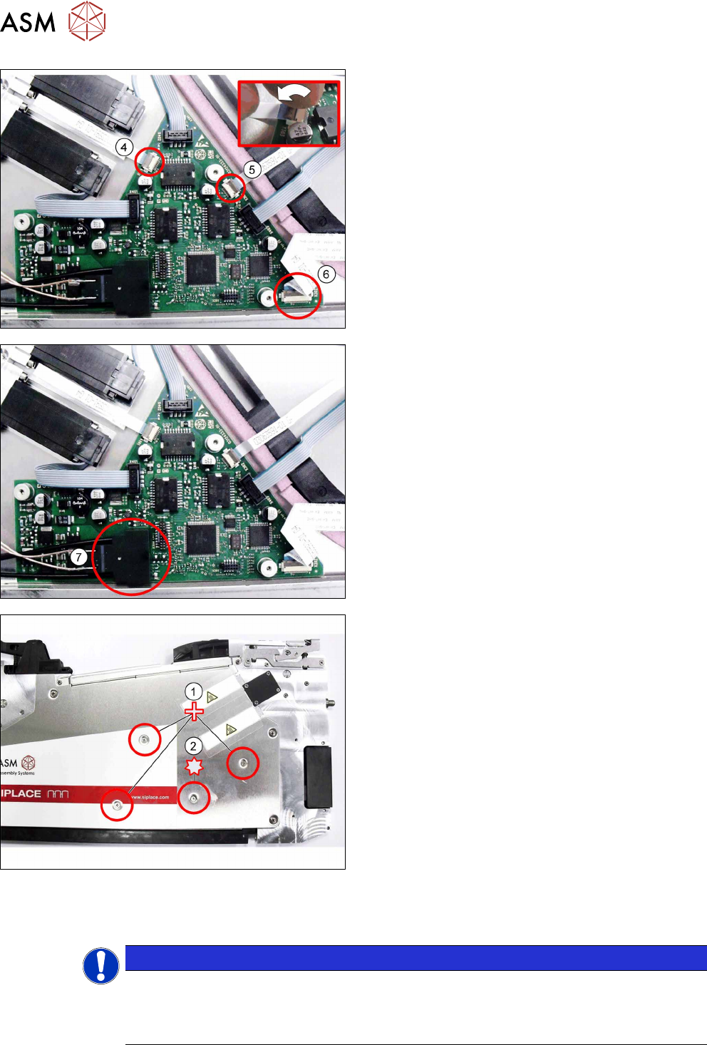
Connect the 3 flat ribbon cables(4-6) to the control
board. Proceed as follows for this:
► Push the flat ribbon cable as far as the stop into
the connection shown in the diagram.
Make sure that the contacts are on the underside
of the cable and that the blue side of the cable
can be seen on the top.
► Lock the connection (see the diagram, top right).
► Insert the EDIF connector (7) into the marked
connection on the control board.
► Align the position of the control board again, us-
ing the 3 holes in the control board and the 3
holes in the side cover.
► Carefully place the feeder module with the left
side down on a stable, level and clean surface,
while holding the control board in its position.
► Fasten the control board with the 3 Phillips screws
shown in the diagram(1)
to the right side cover.
► Make sure that the EDIF connector is correctly in-
serted onto the control board.
► Carefully fasten the EDIF connector with the TORX
screw shown in the diagram(2)
.
Use a size T8 TORX screwdriver with 0.2 Nm. for this.
► Carefully place the feeder module with the right
side down on a stable, level and clean surface.
► Fasten the left side cover (see section 6.3.2 "Fit-
ting the Left Side Cover" [}30]).
NOTICE
Reference run
After replacing the control board, it is essential that you perform a reference run of the
feeder module! For a detailed description, refer to section6.16.3
"Performing a reference
run" [}85].