Service Manual SIPLACE SmartFeeder.pdf - 第186页
8 Repairs to SmartFeeder 2x8 mm X / Xi 8.6 Sealing elements on pin wheel 186 Service Manual SIPLACE SmartFeeder 4 - 8 mm X / Xi SIPLACE SmartFeeder 2 x 8 mm X / Xi 11/2020 8.6.1 Removing the sealing elements from the pin…
8 Repairs to SmartFeeder 2x8 mm X / Xi
8.6 Sealing elements on pin wheel
Service Manual SIPLACE SmartFeeder 4 - 8 mm X / Xi SIPLACE SmartFeeder 2 x 8 mm X / Xi 11/2020 185
8.6 Sealing elements on pin wheel
Spare part required
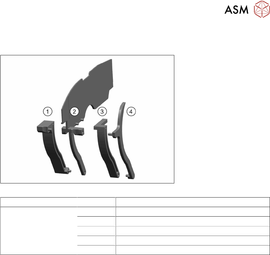
Fig.60: Set of sealing elements X2x8
Feeder module Position Designation
SmartFeeder 2x8 mm X 1, 2, 3, 4 Set of sealing elements X2x8 [03078746Sxx]
1 Seal for pin wheel right assy. X2x8
2 Seal for pin wheel middle assy. X2x8
3 Seal for pin wheel middle left assy. X2x8
4 Seal for pin wheel left assy. X2x8
Tools and consumables required
●
TORX screwdriver size T8
●
Phillips screwdriver
●
Tweezers
●
Allen key size 4
8 Repairs to SmartFeeder 2x8 mm X / Xi
8.6 Sealing elements on pin wheel
186 Service Manual SIPLACE SmartFeeder 4 - 8 mm X / Xi SIPLACE SmartFeeder 2 x 8 mm X / Xi 11/2020
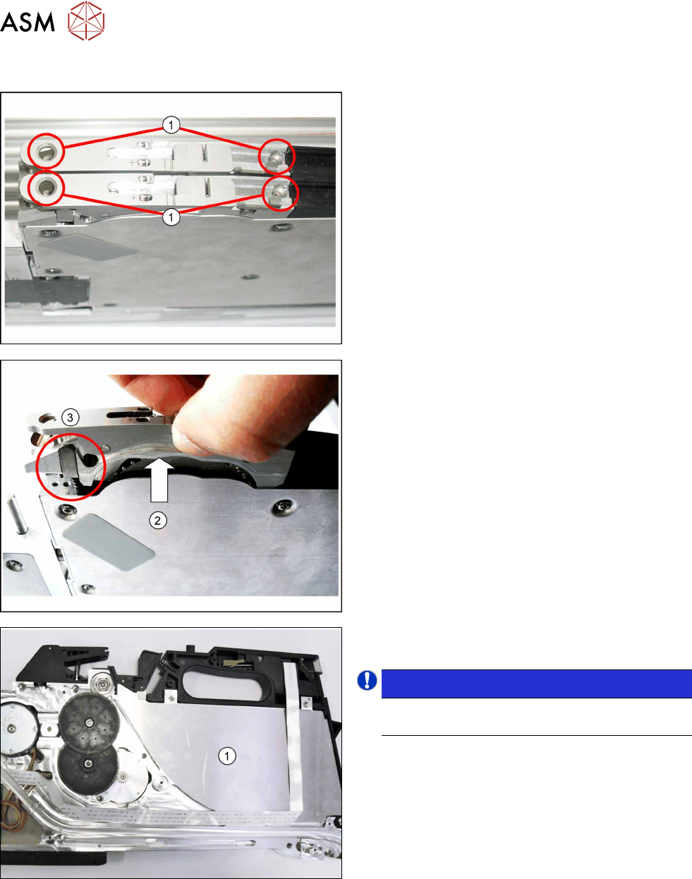
8.6.1 Removing the sealing elements from the pin wheel
► Remove the 4 marked screws (1) fastening the
relevant pickup window and tape duct to the
feeder module.
► Lift the pickup window up and off, together with
the tape duct.(2)
► Also remove the pressure spring and the pres-
sure bracket, to prevent these being lost.(3)
► Remove the left side cover (see section 8.3.1
"Removing the Left Side Cover" [}174]).
► Remove the outer panel(1) from the left foil con-
tainer.
NOTICE!
Take note: the outer panel is only placed on top
and could fall out.
.
8 Repairs to SmartFeeder 2x8 mm X / Xi
8.6 Sealing elements on pin wheel
Service Manual SIPLACE SmartFeeder 4 - 8 mm X / Xi SIPLACE SmartFeeder 2 x 8 mm X / Xi 11/2020 187
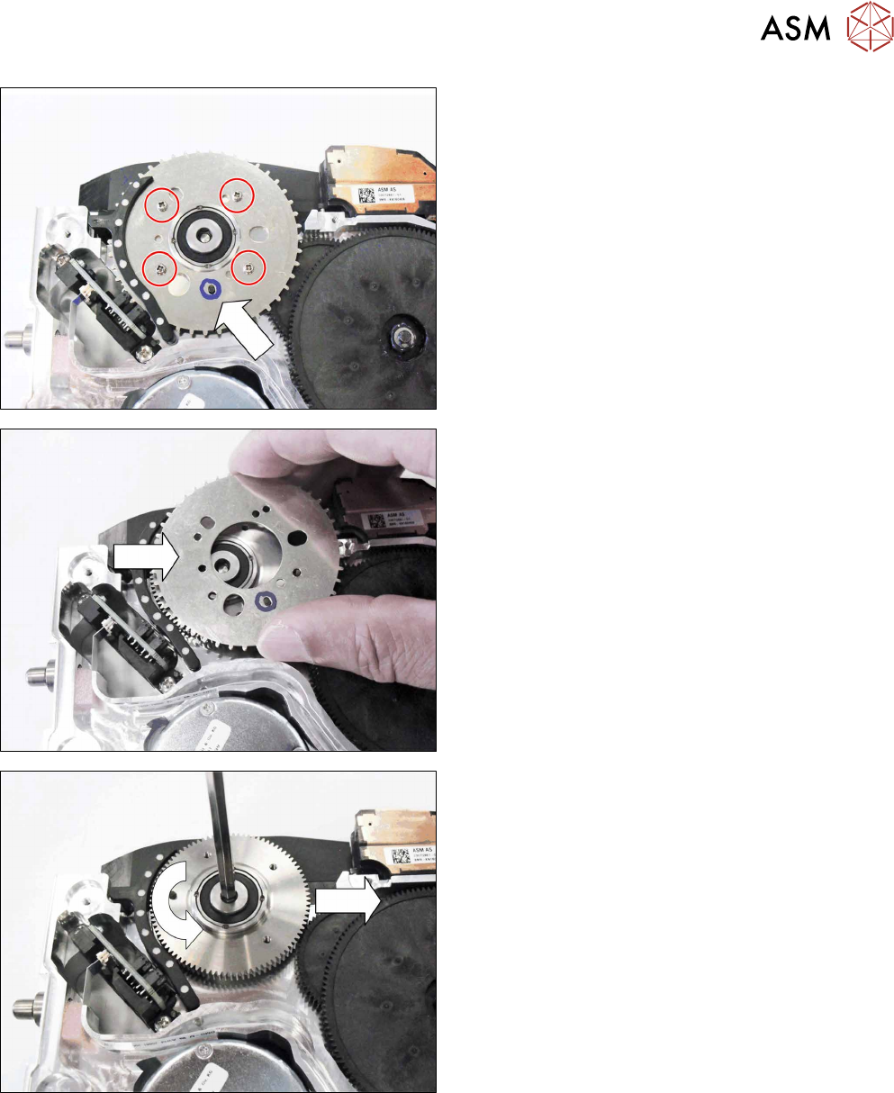
The pin crown on the left track is fastened to the pin
wheel base below it with 4 screws.
The positioning of the pin crown to the pin wheel base
is set with the help of a pin.
► To make subsequent assembly easier, mark the
hole in which the pin is currently located.
► Remove the 4 screws marked.
► Carefully lift off the pin crown.
► Pull the pin crown to the right and out of the seal-
ing elements.
► Use an Allen screwdriver, size 4, to loosen the
pin wheel base bearing.
► Remove the pin wheel base.
► Remove the right side cover (see section 8.3.3
"Removing the Right Side Cover" [}175]).