Service Manual SIPLACE SmartFeeder.pdf - 第86页
6 Repairs to SmartFeeder 4 mm X / Xi 6.17 Foil container 86 Service Manual SIPLACE SmartFeeder 4 - 8 mm X / Xi SIPLACE SmartFeeder 2 x 8 mm X / Xi 11/2020 6.17 Foil container 6.17.1 Replacing the insertion foil container…
6 Repairs to SmartFeeder 4 mm X / Xi
6.16 Control board
Service Manual SIPLACE SmartFeeder 4 - 8 mm X / Xi SIPLACE SmartFeeder 2 x 8 mm X / Xi 11/2020 85
6.16.3 Performing a reference run
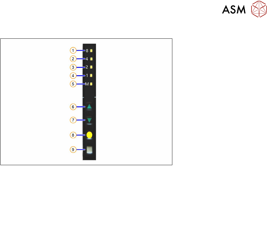
Fig.25: Control panel
1. LED 8 – 8mm pitch
(active only on SmartFeeder 8mmX)
6. FORWARDS button
2. LED 4 – 4mm pitch 7. BACKWARDS button
3. LED 2 – 2mm pitch 8. FOIL button
4. LED 1 – 1mm pitch 9. SET button
5. LED M – menu
Shines when an operator menu is active
► Place the feeder module on a single slot EDIF or on a changeover table for X feeders which is
connected to a placement machine.
► Press and hold the gray SET button(9) until the reference run is enabled.
► Press the yellow foil button three times briefly(8).
After the first press of the FOIL button, the LEDM will switch on.
After the second press, LED1 will also be switched on.
After the third press, LED2 will also be switched on.
The menu for enabling the reference run has now been selected.
► In addition to the SET button, also press the FORWARDS button(7).
LED8(1)
should now flash rapidly. If LED8 and LED4(2) flash, this indicates that there is a
feeder module error present (e.g. foil is tensioned or tape drive has an error) and the refer-
ence run can not be performed.
► Release the FORWARDS button.
The reference run will start.
► Release the SET button.
The reference run will be automatically finished. The control panel will then switch over to the
pitch display.
6 Repairs to SmartFeeder 4 mm X / Xi
6.17 Foil container
86 Service Manual SIPLACE SmartFeeder 4 - 8 mm X / Xi SIPLACE SmartFeeder 2 x 8 mm X / Xi 11/2020
6.17 Foil container
6.17.1 Replacing the insertion foil container
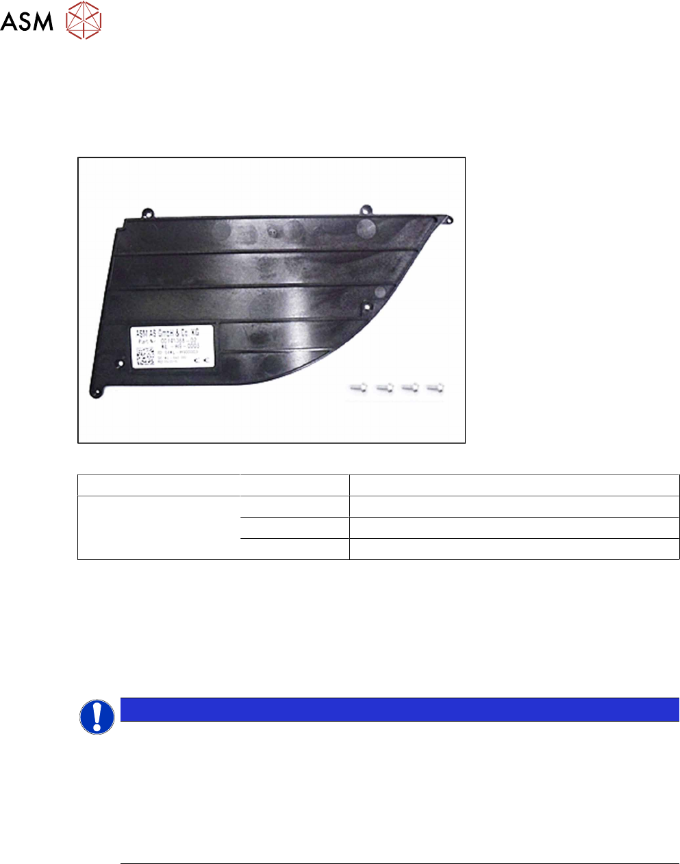
Spare part required
Fig.26: Insertion foil container X4Smart V2
Feeder module Item no. Designation
SmartFeeder 4mmX
SmartFeeder 4mmXi
03126541Sxx Insertion foil container X4Smart V2
03033796-xx RF-SN75-2.5 x 6-9.8
03010209-xx ISO 7045 - M2.5 x 6-A2-50-H
Tools required
●
Phillips screwdriver 0.9Nm
●
TORX screwdriver 0.6Nm, size T8
●
Phillips screwdriver
6.17.1.1 Cleaning or replacing the foil container
NOTICE
Risk of confusion
The "insertion foil container X4Smart V2" has a label with details about the feeder module
(item number, serial number, barcode,…).
When replacing the insertion foil container, you need to create an identical new label and
attach it to the feeder module, so that the feeder module can be clearly identified again
after the replacement.
For a description of how to create new labels, see section 2.5 "Creating new labels for
feeder modules" [}15].
► Carefully place the feeder module with the left side down on a stable, level and clean surface.
► Remove the right side cover (see 6.3.3 "Removing the Right Side Cover" [}31]).
6 Repairs to SmartFeeder 4 mm X / Xi
6.17 Foil container
Service Manual SIPLACE SmartFeeder 4 - 8 mm X / Xi SIPLACE SmartFeeder 2 x 8 mm X / Xi 11/2020 87
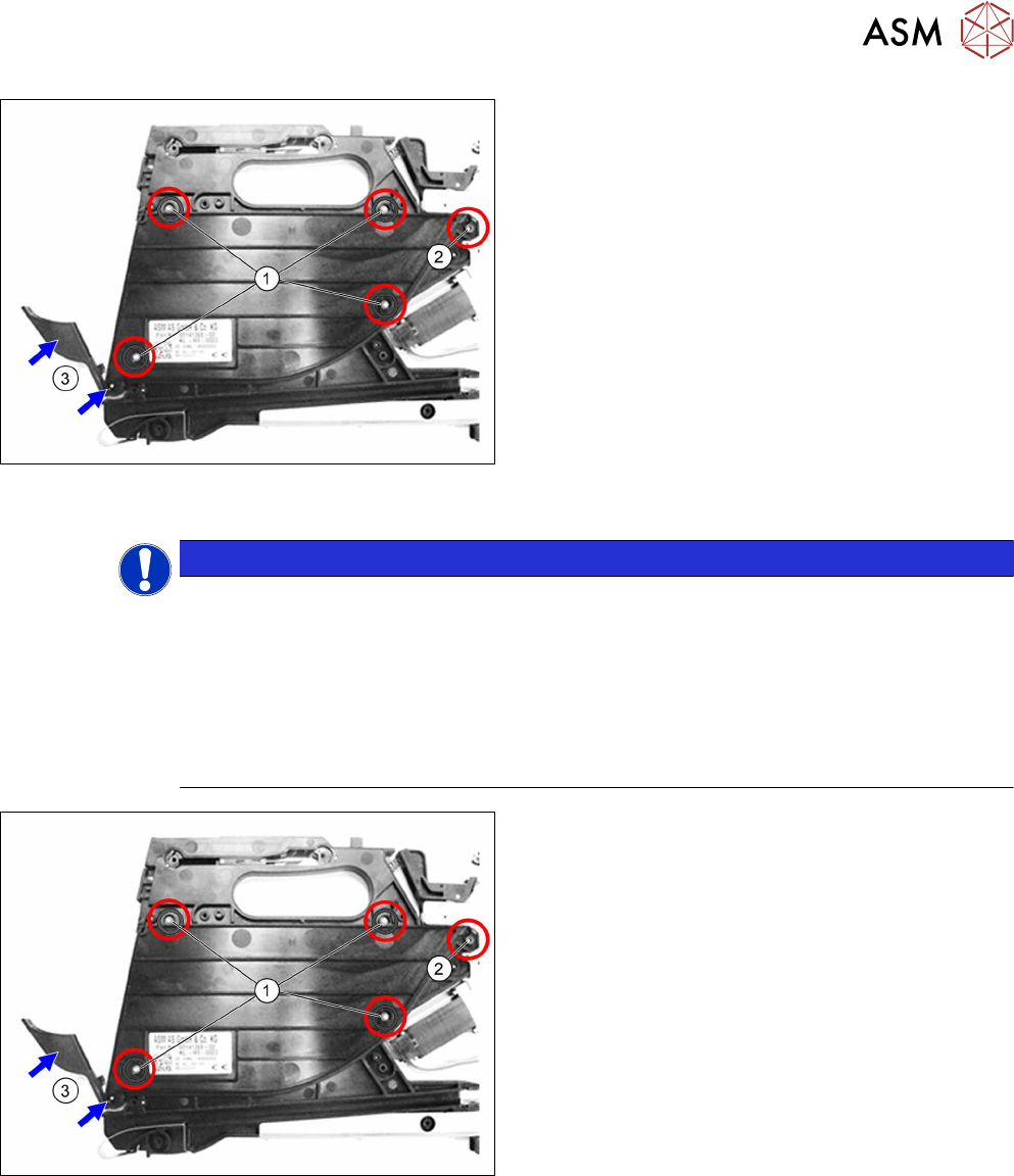
If you want to replace the insertion foil container:
► Remove the 4 TORX screws marked in the dia-
gram. (1)
Use a T8 TORX screwdriver for this.
► Remove the Phillips screw marked in the dia-
gram. (2)
► Remove the cover flap with the shaft.(3)
► Carefully remove the insertion foil container.
If you don't want to replace the insertion foil container:
► Clean the foil container thoroughly and remove
all foil and adhesive residues.
6.17.1.2 Fitting the foil container
NOTICE
Risk of confusion
The "insertion foil container X4Smart V2" has a label with details about the feeder module
(item number, serial number, barcode,…).
When replacing the insertion foil container, you need to create an identical new label and
attach it to the feeder module, so that the feeder module can be clearly identified again
after the replacement.
For a description of how to create new labels, see section 2.5 "Creating new labels for
feeder modules" [}15].
► Carefully place the feeder module with the left
side down on a stable, level and clean surface.
► Inserting the (new) insertion foil container.
► Fasten the insertion foil container with the 4
TORX screws marked in the diagram
(RF‑SN75‑2.5 x 6‑9.8, 03033796‑xx).(1)
Use a TORX screwdriver 0.6Nm, size T8 for this.
► Fasten the Phillips screw (ISO 7045 - M2.5 x 6-
A2-50-H, 03010209‑xx).(2)
► Insert the shaft in the position shown into the in-
sertion foil container, as far as the stop.(3)
► Push the flap onto the shaft.(3)
► Fit the right side cover (see6.3.4 "Fitting the Right Side Cover" [}32]).