YSM40R_Mainte_E.pdf - 第101页
3-31 3 Periodic maintenance items 2.5 Feeder exchange carriage 2.5.1 Cleaning/lubricating carriage cam followers 1 Detach feeder ex change carriage. Unclamp and lower the feeder exchange carriage with the CLAMP ON/OFF sw…
3-30
3
Periodic maintenance items
2.4 Base section and others
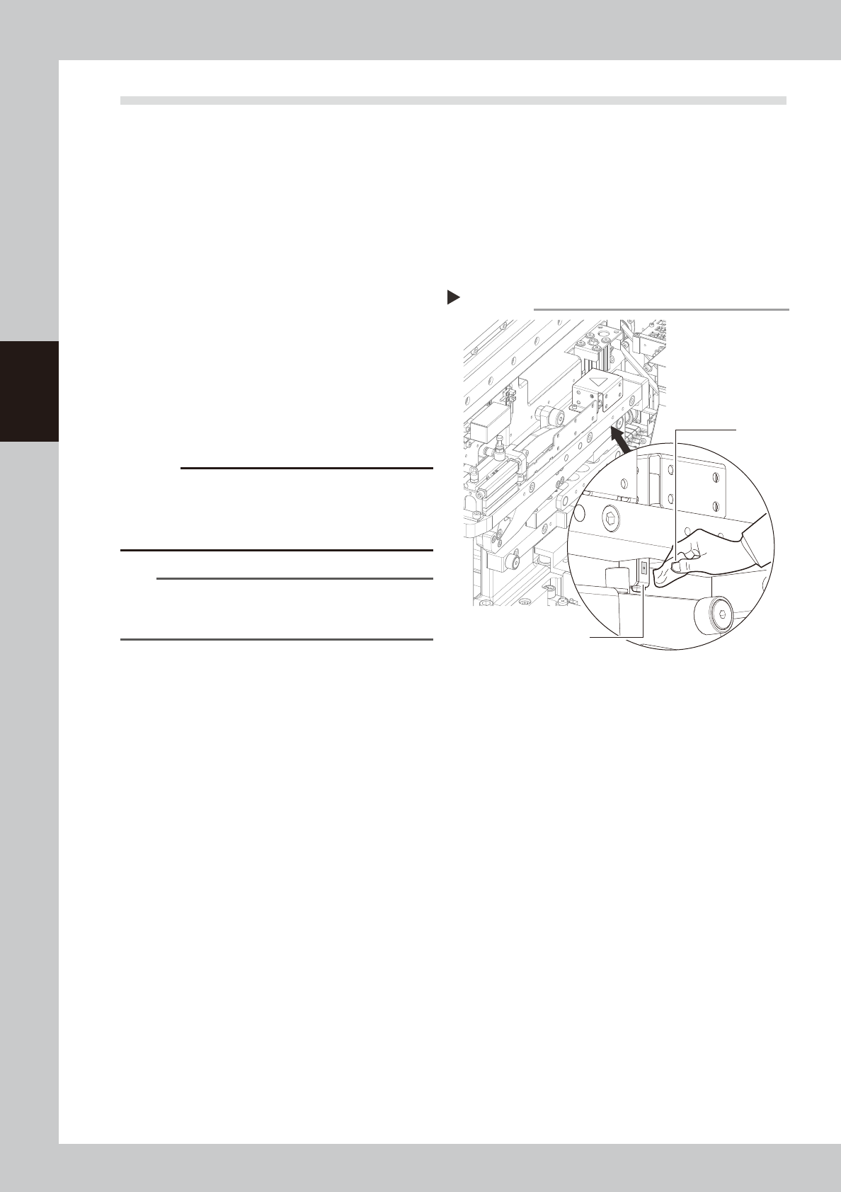
2.4.1 Cleaning feeder float sensor
This section describes the procedure for cleaning the feeder float sensor that detects whether tape feeders are
correctly installed on the feeder plate.
1
Prepare for work.
e
1. Remove all items sensitive to magnetic fields such as wristwatches and magnetic ID cards.
2. Press the emergency stop button and then open the machine safety cover.
3. Use the CLAMP ON/OFF switch to lower the feeder exchange carriage and detach it.
2
Remove dust from the sensor unit.
Use a blower brush to remove any dust from
the sensor area.
53332-N9-00
3
Clean the sensor.
Clean the sensor's surface using a cotton
swab or a cloth dampened with a small
amount of IPA.
c
CAUTION
Pressing the sensor too much may cause the optical
axis to deviate.
Avoid applying excessive force when cleaning the
sensors.
n
NOTE
Machines with a cATS are also equipped with a feeder
float sensor. Clean that sensor with the same procedure
as used for machines with a feeder exchange carriage.
Cleaning the feeder float sensor
Step 2, 3
Feeder float sensor
Cloth
3-31
3
Periodic maintenance items
2.5 Feeder exchange carriage
2.5.1 Cleaning/lubricating carriage cam followers
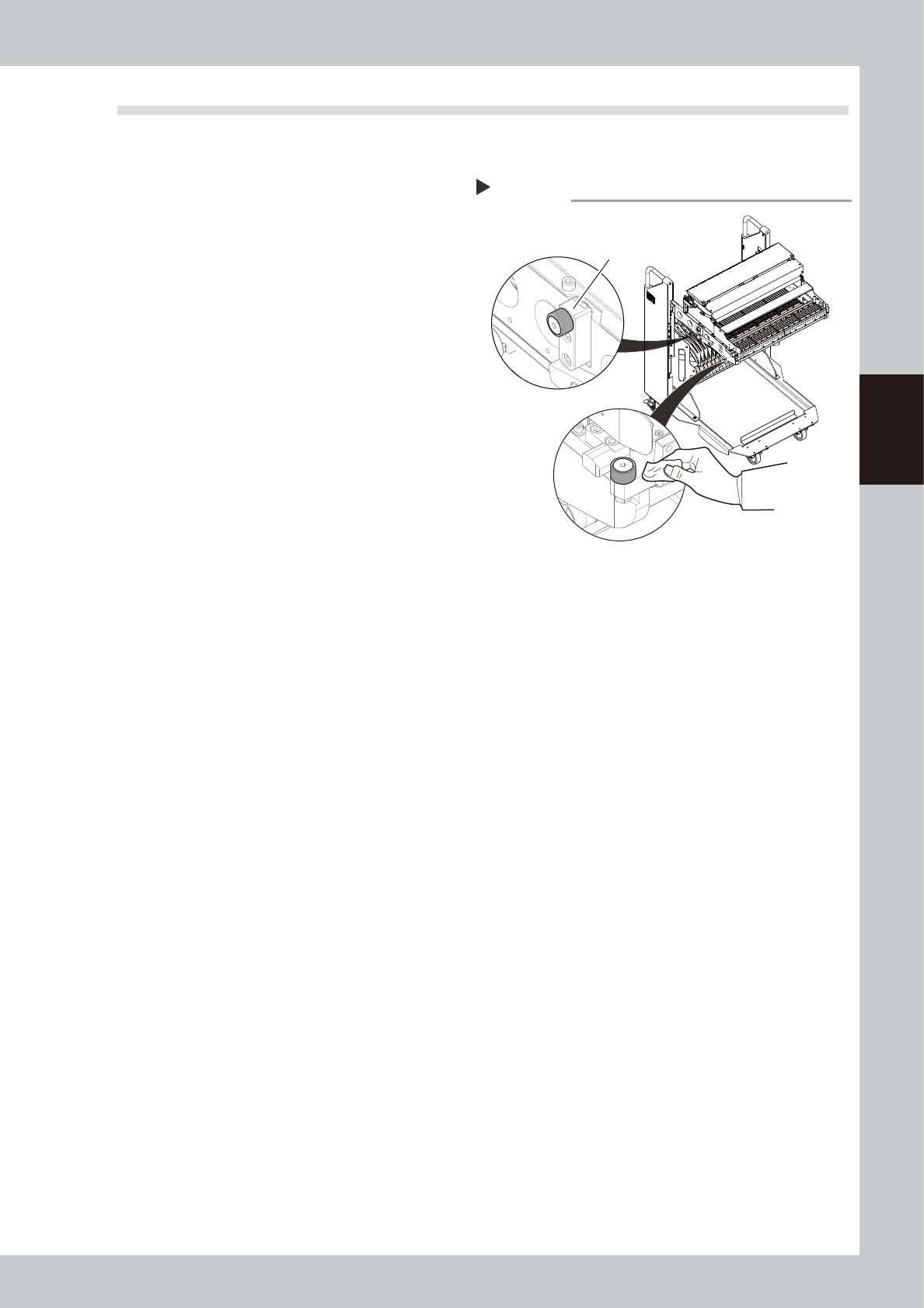
1
Detach feeder exchange carriage.
Unclamp and lower the feeder exchange
carriage with the CLAMP ON/OFF switch and
detach it from the machine.
2
Clean the carriage cam followers.
Use a lint-free cloth to wipe off the grease
and dirt on the cam followers (3 places per
carriage).
53333-N9-00
3
Apply grease to the cam followers.
Apply a uniform coat of the specified grease
(NSL) by hand to the cam followers.
Cleaning the carriage cam followers
Step 2
Cam follower at rear of carriage
(one each on right and left sides)
Cam follower at front of carriage
(one on left side)
3-32
3
Periodic maintenance items
2.6 RS head
How to lower RS head/nozzle shafts
Maintenance of the RS head requires lowering the nozzle shafts manually in sequence as for example in "2.6.1
Inspecting and replacing the air filters" and "3.2.1 Inspecting/cleaning nozzle shaft tip". This method is
described below.
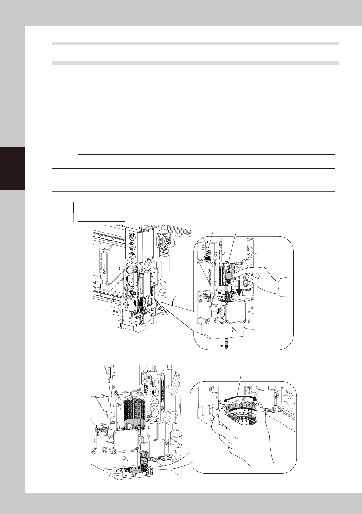
1
Press down Z-axis of RS head.
The Z-axis units are located on both sides of RS head unit for lowering nozzle shafts. The nozzle shafts
under Z-axis can be lowered by pressing down Z-axis manually.
2
Change the nozzle shaft to be lowered.
Move a nozzle shaft under Z-axis by gripping and turning the rotary unit’s label ring (part on which the
nozzle shaft numbers are printed) located on the bottom of RS head.
c
CAUTION
Make sure that all nozzle shafts have returned to upper end after having lowered the nozzle shafts manually,
n
NOTE
The rotary unit can also be turned by turning the R-axis gear manually.
R-axis gear
Changing nozzle shaft to be lowered
Lowering RS head/nozzle shaft
Z-axis unit of
RS head
*Also located on
the opposite side
Press down Z-axis on both sides of
RS head to lower nozzle shaft.
Lowering nozzle shaft
Grip the label ring (part on which the nozzle
numbers are printed) and turn the rotary unit.
533D6-N9-00