YSM40R_Mainte_E.pdf - 第200页
Appendix Appendix Contents 1. Specifications A-1 1.1 Air regulator unit A-1 1.2 Power connection terminals A-2 1.3 Connection between machines A-3 1.3.1 PREVIOUS INTERF ACE connector A-3 1.3.2 NEXT INTERF ACE connector A…
6-9
6
How to replace consumable parts
3.2 Replacing nozzle O-ring
e
1
Detach the nozzle.
1. Press the emergency stop button to put
the machine in the emergency stop
state.
2. Turn off the carriage clamp switch to
detach carriage from mounter.
3. Detach relevant nozzle manually.
2
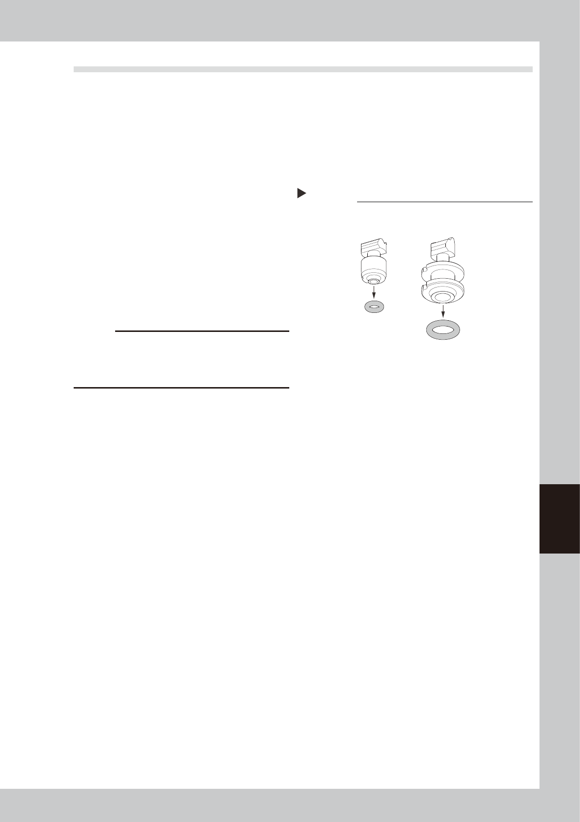
Replace the nozzle O-ring.
Detach the O-ring and replace it with a new
one. If the O-ring is difficult to detach,
detach it with a precision slotted
screwdriver.
53616-N9-00
3
Return the nozzle to its original
position.
Return the nozzle you have detached to the
head.
c
CAUTION
Be sure to return the nozzle you have detached to its
mating head. When the nozzle has been detached from
the nozzle station (option), return it correctly to the
storage position where you have detached the nozzle.
Replacing the nozzle O-ring
Step 2
604A Nozzle
Removing the O-ring
504A Nozzle

Appendix
Appendix
Contents
1. Specifications A-1
1.1 Air regulator unit A-1
1.2 Power connection terminals A-2
1.3 Connection between machines A-3
1.3.1 PREVIOUS INTERFACE connector A-3
1.3.2 NEXT INTERFACE connector A-4
2. Maintenance parts A-5
2.1 YSM40R main unit maintenance parts list A-5
2.2 Tray component supply unit maintenance parts list A-14
A-1
Appendix
1. Specifications
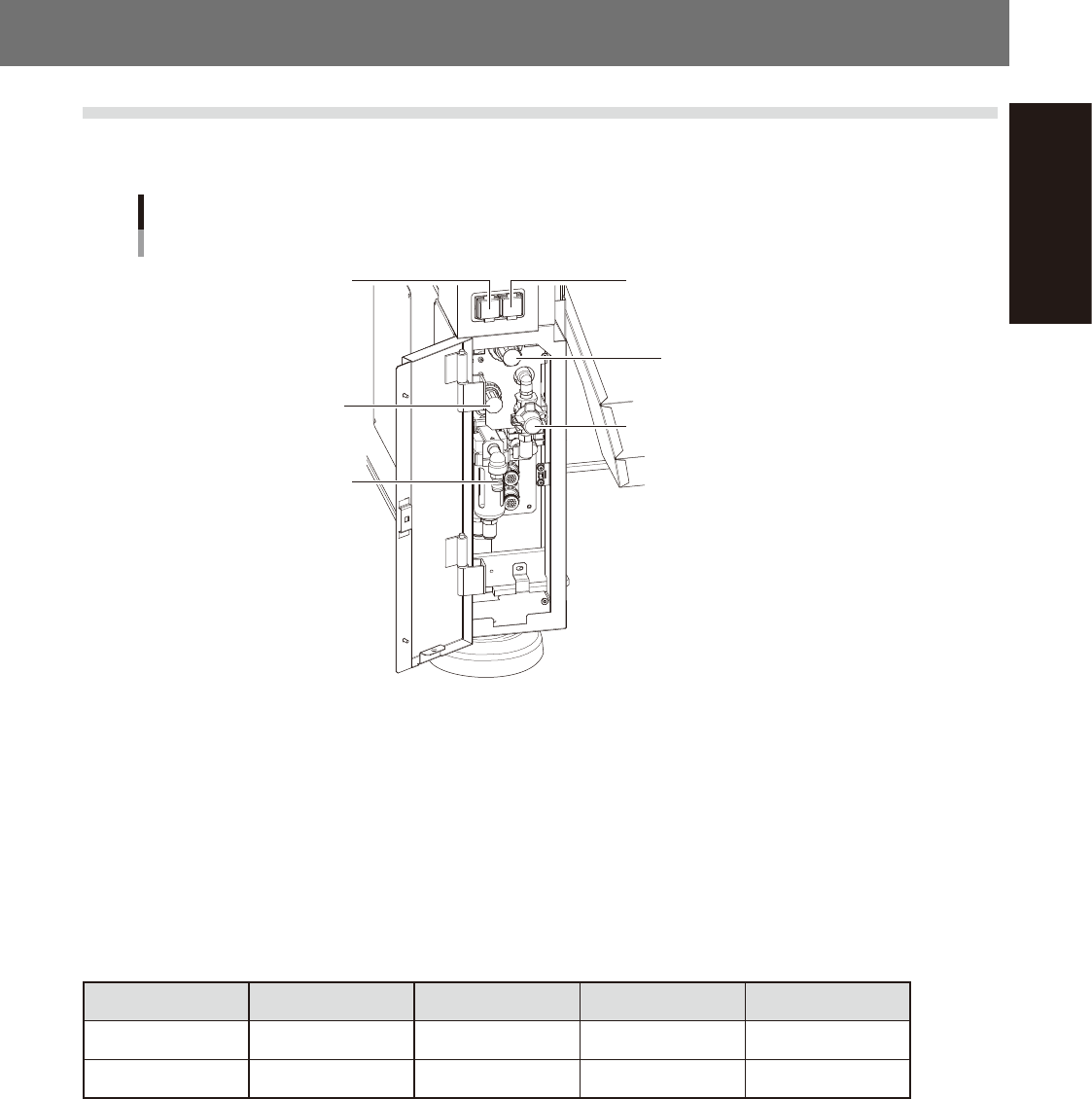
1.1 Air regulator unit
The air regulator for controlling the air pressure to the machine's pneumatic units is located at the lower left
panel on the rear side of the machine. Specify the appropriate air pressure setting shown below.
Air pressure regulator and pressure gauge
Setting air pressure gauge
[PNEUMATIC]
Setting air pressure regulator
[PNEUMATIC]
Air supply/exhaust switch
Head air pressure gauge
[HEAD BLOW]
Head air pressure regulator
[HEAD BLOW]
Source air connector
53A01-N9-00
n
Supply air pressure
This is the pressure of the source air supplied to the machine. Before setting the air pressure with the air regulator, make
sure that this supply air pressure is in the following optimal range.
YSM40R : 0.45MPa to 0.70MPa
n
Air pressure gauge (display)
When within the normal range, the air pressure displays in green. When the air pressure is beyond the upper/lower limit
values (air down detection), an error occurs, and the air pressure displays in red.
n
Air pressure setting values and upper/lower limit values
Head Setting Value Lower Limit Value Upper Limit Value
Setting air pressure Common 0.40Mpa (±0.01) 0.39Mpa 0.41Mpa
Head air pressure Common 0.040Mpa (±0.001) 0.039Mpa 0.041Mpa
n
Air supply/shutoff switch (valve)
Turning this switch to the right shuts off air supply and exhausts air that remains inside the machine.
n
Source air connector
Prepare an air hose with an inner diameter of at least 8 mm having a 40SH socket (Nitto Koki, or equivalent), and
connect it to this connector. Use dry, clean air passed through an air filter.