YSM40R_Mainte_E.pdf - 第58页
2-3 2 Daily maintenance items Detaching tape cutter duct T he feeder exchange carriage and tape cutter duct can be detached to make it easier to access to the mac hine interior during maintenance work. The procedure for …
2-2
2
Daily maintenance items
n
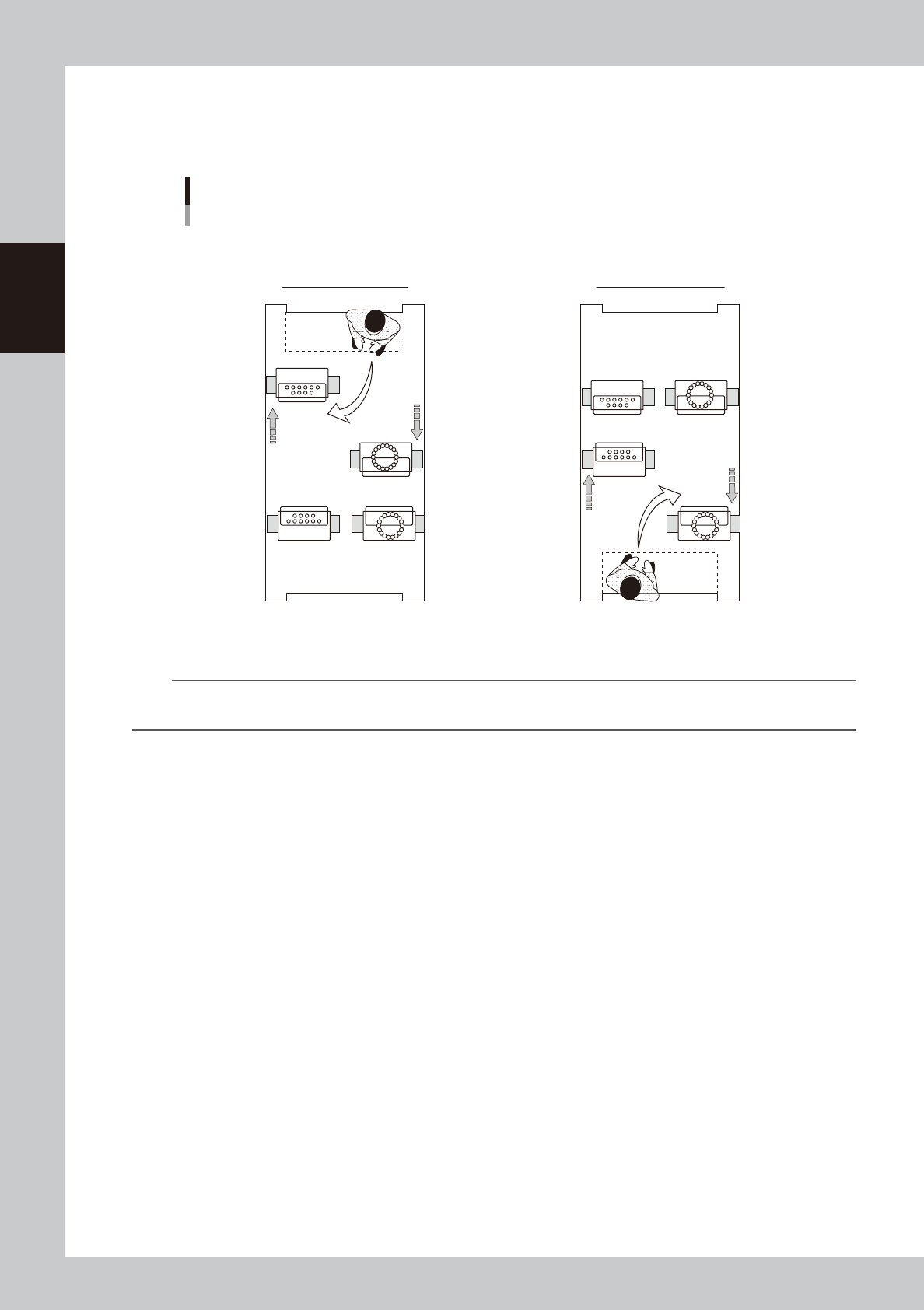
Maintaining 4-beam head units
When maintaining 4-beam head units, move the relevant head unit only to front. Then access to the head unit as shown
in the figure below.
D
B
C
A
D
B
C
A
Head units
4-beam type (Example: MU/RS heads)
■ Maintaining head units
Maintaining rear head unit Maintaining front head unit
Machine front
Machine front
53206-N9-00
n
NOTE
Pressing the [Head Pos. Front] and [Head Pos. Rear] buttons on "Setup" screen before moving head unit is convenient
for maintenance task.
2-3
2
Daily maintenance items
Detaching tape cutter duct
The feeder exchange carriage and tape cutter duct can be detached to make it easier to access to the machine
interior during maintenance work. The procedure for detaching the duct is described below.
n
NOTE
Some maintenance procedures described in this manual include instructions on detaching a feeder exchange
carriage. if it is still not easy to perform the maintenance work with detaching carriage, detach the tape cutter duct
as needed to make the work easier.
e
1
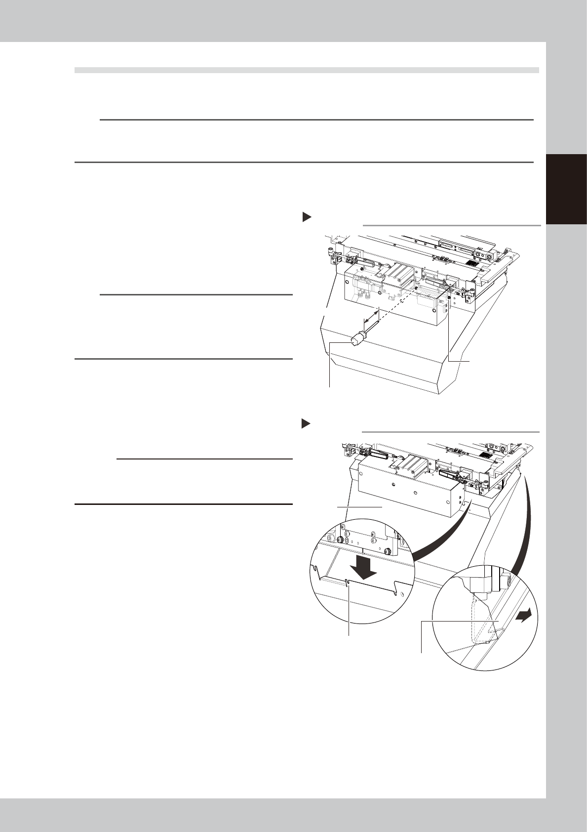
Detach the feeder exchange
carriage.
Press the emergency stop button and then
detach the feeder exchange carriage.
2
Loosen the duct mounting screws.
Use a Phillips screwdriver to loosen 4 duct
mounting screws as shown in the figure at
right.
n
NOTE
Do not completely remove the duct mounting screws.
The duct can be detached simply by partially loosening
the screws.
Use a Phillips screwdriver with a shaft length longer than
100 mm.
53200-N9-00
3
Detach the duct.
As shown in the figure at right, slightly slide
the front side of the duct downward and
then unhook the rear hook to detach the
duct.
c
CAUTION
As the duct will fall when all screws are loosened,
loosen the final screw while supporting the duct from
below.
53201-N9-00
4
Return the duct to original position.
After the maintenance work, etc. has been
completed, Return the duct to original
position in reverse order of detaching.
Remove the duct
Step 3
Duct
Duct securing bolt
position (notched)
Hook
Loosening duct mounting screws
Step 2
Duct mounting screws
(4 pcs)
Phillips screwdriver
Longer than 100 mm
2-4
2
Daily maintenance items
1. Checking the nozzle
Solder sticking to the nozzle tip or a clogged nozzle hole can cause component pickup error and recognition
error. Inspect each nozzle periodically to prevent the errors.
1.1 Checking with software
n
How to check for a dirty nozzle (with the [Tip Dirt Check] button)
The term "dirty nozzle" as used here indicates shiny material such as solder adhering to the nozzle tip. This
shiny portion might be mistaken for a component and cause recognition errors. [Tip Dirt Check] is a tool that
judges the nozzle contamination status by recognizing the nozzle tip in the non-component status with the
camera. Regarding RS head, this function is available with machine equipped with multi-camera.
n
NOTE
The [Tip Dirt Check] is a function that recognizes the reflection of the light around the nozzle center. Therefore,
applicable nozzles are those with a small tip, such as Type 501A and 502A.
n
NOTE
As the nozzle type may vary depending on the machine, some machines may require additional settings. Contact
YAMAHA sales representatives for details.
1
(Without nozzle station) Replace
the nozzle.
1. Press the [Required Nozzles] button on
the "Setup" screen to check the nozzles
to be used for production.
e
2. Press the emergency stop button and
then open the machine safety cover.
3. Attach nozzles to be used for production
to head.
4. Close the machine safety cover and
then cancel the emergency stop.
n
NOTE
Step 1 can be skipped if the machine is equipped with
the nozzle station.
2
Press the [Tip Dirt Check] button
on the "Setup" screen.
54200-N9-00
Pressing the [Tip Dirt Check] button
Step 2
[Tip Dirt Check] button