YSM40R_Mainte_E.pdf - 第94页
3-24 3 Periodic maintenance items 5 Wipe off the ex cess grease. 1. Move the head unit to one end. 2. Wipe off excess grease from the ball screw and its end face. 3. Move the head unit to the opposite end and wipe off ex…
3-23
3
Periodic maintenance items
2.2 X-Y axis (2-beam type)
This section describes the inspection, cleaning, and lubrication procedures for 2-beam type machines. For
details on the lubrication points and schedule, see "Chapter 5 Lubricating points". Prepare grease guns
(standard nozzle and bent nozzle types) and the specified grease (NSL).
2.2.1 Cleaning/greasing X-axis ball screw (2-beam type)
1
Prepare for work.
e
1. Remove all items sensitive to magnetic fields such as wristwatches and magnetic ID cards.
2. Press the emergency stop button and then open the machine safety cover.
3. Use the CLAMP ON/OFF switch to lower the feeder exchange carriage and detach it.
4. Place a square cloth on each Y-axis linear guide and push-up plate.
2
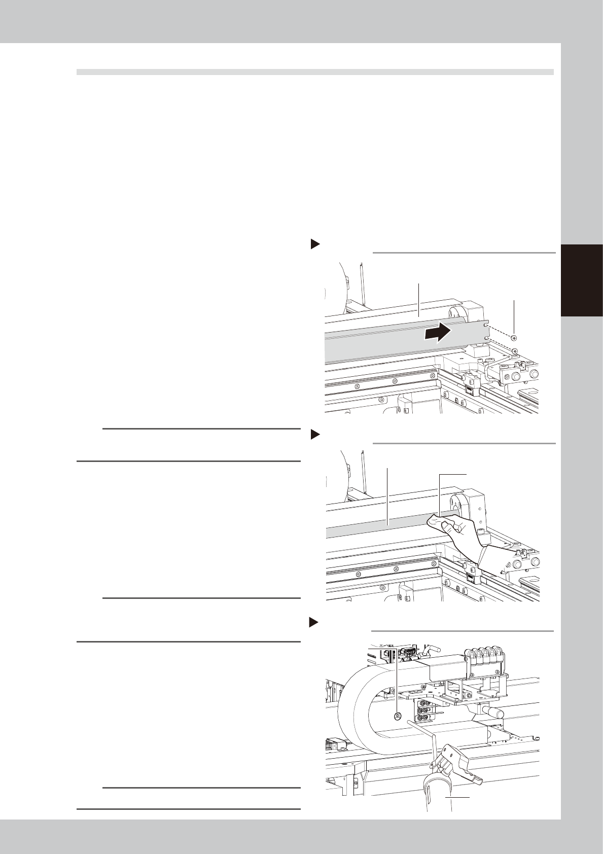
Detach the grease spattering
prevention cover.
Detach the X-axis grease spatter prevention
cover.
1. Loosen mounting screws for grease
spattering prevention cover (motor side)
with Phillips screwdriver.
2. Move the head unit to the motor side.
3. Remove mounting screws for grease
spattering prevention cover at the side
opposite to motor side with Phillips
screwdriver. Then pull out the grease
spattering prevention cover.
53321-N9-00
TIP
Reattach the X-axis grease spatter prevention cover by
reversing the above removal procedure.
3
Clean the ball screws.
1. Move the head unit to one end.
2. Wipe away the old grease and dirt from
the ball screw with a lint-free cloth or
paper towel (for clean room use).
3. Move the head unit to the opposite end
and wipe the opposite-side ball screw.
53322-N9-00
n
NOTE
When cleaning the ball screw, carefully clean its
groove area as well. After cleaning, make sure that no
dust, lint and debris remain on the ball screw.
4
Apply grease.
1. As shown in the figure at right, move the
head unit by hand to a position where
the grease nipple is visible through the
access window.
2. Use a grease gun (30° bend type) to
inject the prescribed grease at the
grease nipple.
53323-N9-00
n
NOTE
Inject until the grease begins to seep out from the gap.
Detaching spatter prevention cover
Step 2
Grease spattering prevention cover
Cover mounting screws
Cleaning the ball screw
Step 3
Cloth
Ball screw
Applying grease
Step 4
Grease nipple
Grease gun
(30° bent type)
3-24
3
Periodic maintenance items
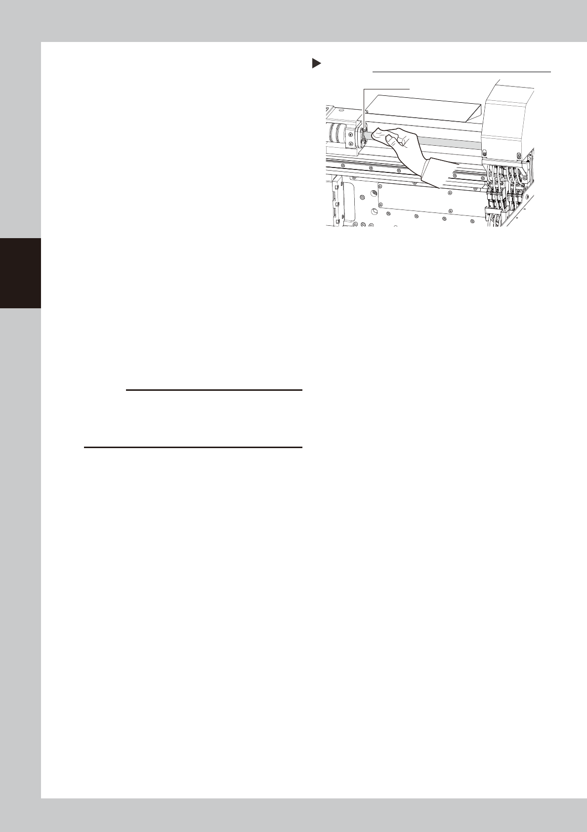
5
Wipe off the excess grease.
1. Move the head unit to one end.
2. Wipe off excess grease from the ball
screw and its end face.
3. Move the head unit to the opposite end
and wipe off excess grease from the ball
screw and its end face on the opposite
side.
53324-N9-00
6
Perform a warm-up.
1. Remove the square cloth.
2. Reattach the spatter prevention cover.
3. Close the machine cover, attach the
feeder exchange carriage, then release
the emergency stop.
4. Open the Warm-up screen, and perform
the warm-up operation for about 8
minutes.
e
7
Check the grease condition.
After warm-up is finished, press the
emergency stop button and remove the
grease spattering prevention cover. Then
wipe off the grease which has collected on
the ball screw and its end faces.
c
CAUTION
Repeat Steps 6 and 7 until grease accumulations no
longer occur. Beginning production with grease
accumulations present could cause the grease to
spatter.
8
Reattach the grease spattering
prevention cover.
Wiping off the excess grease
Step 5
Excess grease
3-25
3
Periodic maintenance items
2.2.2 Cleaning/Lubricating X-axis guides, Cleaning linear scale (2-beam type)
1
Prepare for the task.
e
1. Remove all items sensitive to magnetic fields such as wristwatches and magnetic ID cards.
2. Press the emergency stop button and then open the machine safety cover.
3. Use the CLAMP ON/OFF switch to lower the feeder exchange carriage and detach it.
4. Place a square cloth on each Y-axis linear guide and push-up plate.
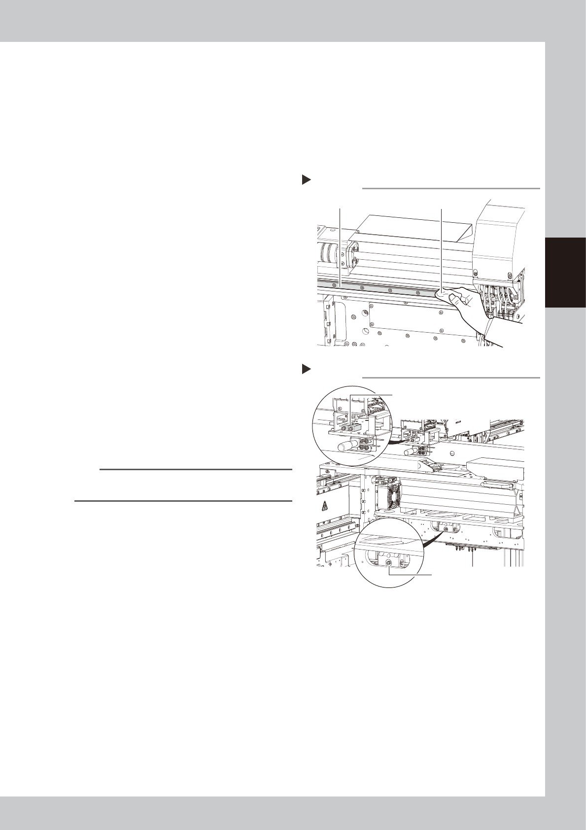
2
Clean the guide.
1. Move the head unit to one end.
2. Using a lint-free cloth (for clean room),
wipe the old grease and soiling from the
entire guide.
3. Move the head unit to the opposite side,
then clean the opposite-side guide.
53325-N9-00
3
Inject the grease.
1. Move the head unit to a position where
the lower guide grease nipple is seen as
shown in the figure at right.
2. Use a grease gun (30° bent type) to
pump the specified grease (NSL) into the
two grease nipples for the upper guide
and also into one grease nipple for the
lower guide.
53326-N9-00
4
Spread the grease.
Move the head right and left several times
manually along the X-axis to spread grease
over the guides.
n
NOTE
The grease injected into the grease nipples comes out
in the guides as the head moves along the X-axis.
5
Remove excess grease.
Wipe off excess grease that has collected at
both ends of the guides.
6
Apply grease again.
Repeat Steps 3 to 5 two more times. Then
visually check that the grease is evenly
applied over the guides.
Cleaning the guide
Step 2
Cloth
Guide
Injecting the grease
Step 3
Grease nipples for upper guide
Grease nipple for lower guide