YSM40R_Mainte_E.pdf - 第153页
3-83 3 Periodic maintenance items 7.2.4 Attaching the replaceable par ts n Attaching the cup packing and pressing plate 1 Place a new cup packing. Place a new packing on the connecting rod, with the sealing side facing d…
3-82
3
Periodic maintenance items
n
Detaching pressing plate and cup packing
1
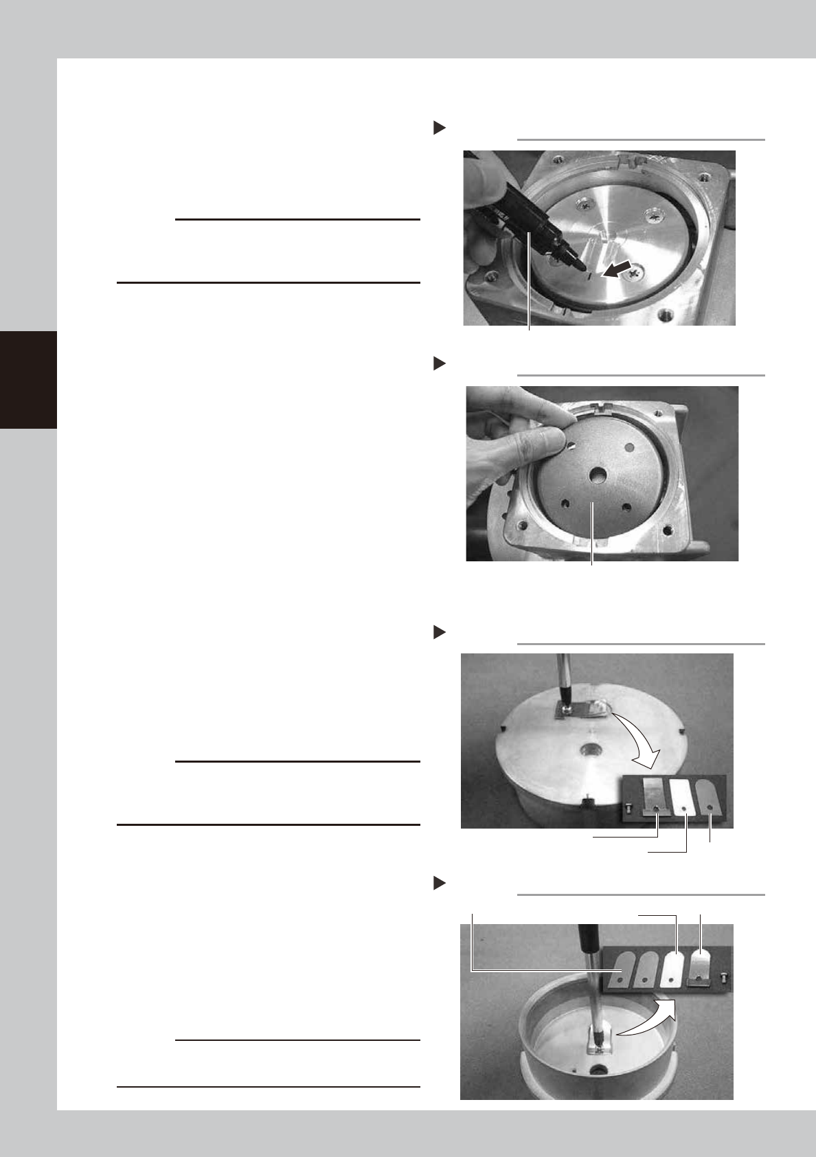
Put a mark.
Using an oil-based marker pen, put a mark
on the pressing plate at the position of the
mark on the casing.
533B2-N9-00
c
CAUTION
The pump will break down if the pressing plate is
reassembled in the wrong direction, so always put a
mark to indicate the reassembly position.
2
Detach the pressing plate.
Always wear gloves and use a Phillips
screwdriver to loosen 4 mounting screws
(M5×L12) and detach the pressing plate.
Clean the detached pressing plate.
3
Detach the cup packing.
533B3-N9-00
n
Detaching cylinder parts
1
Detach the parts on the exhaust
valve side.
Use a Phillips screwdriver to loosen the
mounting screw and detach the exhaust
valve pressing plate, exhaust valve, and
exhaust valve backup.
533B4-N9-00
c
CAUTION
Do not dispose of the exhaust valve pressing plate and
intake valve pressing plate as they will be reused after
cleaning.
2
Detach the parts on the intake
valve side.
Invert the cylinder, loosen the mounting
screw with a Phillips screwdriver, and detach
the intake valve pressing plate, intake valves
(2 pieces), and intake valve backup.
533B5-N9-00
3
Clean the cylinder.
Using a lint-free cloth moistened with a
cleaning solvent, wipe the entire cylinder.
c
CAUTION
During cleaning, be careful not to erase the mark you
put on the cylinder.
Step 1
Marking
Oil-based marker pen
Step 3
Detaching cup packing
Cup packing
Step 1
Detaching exhaust valve
Exhaust valve
Exhaust valve pressing plate
Exhaust valve backup
Step 2
Detaching intake valve
Intake valves (2 pieces) Intake valve pressing plate
Intake valve backup
3-83
3
Periodic maintenance items
7.2.4 Attaching the replaceable parts
n
Attaching the cup packing and pressing plate
1
Place a new cup packing.
Place a new packing on the connecting
rod, with the sealing side facing down.
533B6-N9-00
2
Place the pressing plate.
Place the cleaned pressing plate on the cup
packing while aligning the mark with the
mark on the casing.
533B7-N9-00
3
Tighten the mounting screws.
1. Make sure the mark on the pressing plate
is aligned with the mark on the casing.
2. Use a torque limiting screwdriver to
tighten 4 screws (M5×L12) uniformly in a
diagonal order.
Tightening torque: 0.55 N·m
n
Attaching the cylinder parts
1
Reassemble the intake valve parts.
1. Place the two intake valves (FLAP) in the
cleaned cylinder and then place the
intake valve backup (SHEET1 FLAP) and
pressing plate on the intake valves.
2. Use a torque limiting screwdriver to
tighten the screw (M3×L5) to a torque of
0.55 N•m while being careful not to
make contact with the periphery of the
concave groove.
533B8-N9-00
2
Reassemble the exhaust valve parts.
1. Invert the cylinder, place the exhaust
valve on the cylinder, and place the
exhaust valve backup.
2. Place the pressing plate on the exhaust
valve, and use a torque limiting
screwdriver to tighten the screw (M3×L5)
while being careful not to make contact
with the periphery of the concave
groove.
Tightening torque: 0.55 N•m
3
Insert the cylinder.
Insert the cylinder in the cup packing
section while aligning the mark on the
cylinder with the mark on the casing.
Step 1
Placing a cup packing
Cup packing
Step 2, 3
Mounting the pressing plate
Mounting boltPressing plateTorque limiting screwdriver
Attaching cylinder parts
Tighten the screw so that the exhaust valve does not
make contact with the periphery of the groove.
Step 1
3-84
3
Periodic maintenance items
n
Assembling the head cover
1
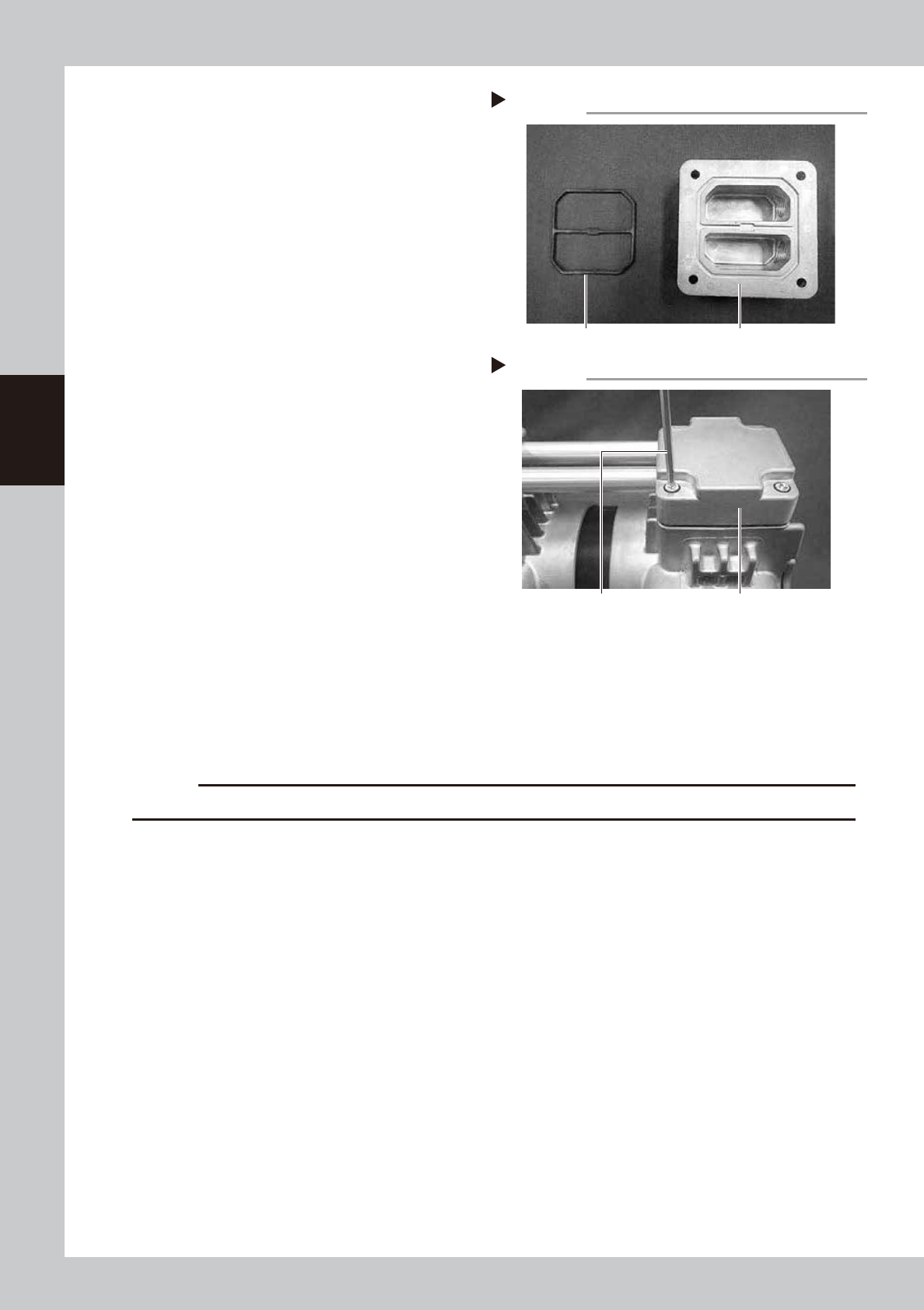
Replace the gasket.
1. Detach the gasket from the head cover
and clean the head cover.
2. Blow air to dry the head cover and then
fit a new gasket in the head cover.
533B9-N9-00
2
Assemble the head covers.
1. Insert the connecting pipe into the head
covers.
2. Align the screw holes in the left and right
casings with the holes in the head
covers, and tighten 4 bolts (M6×L30)
each (total of 8 bolts) using a torque
limiting screwdriver.
Tightening torque: 8 N•m
533C1-N9-00
3
Reattach the panel.
Place the pump on its side and attach the
panel.
7.2.5 Attaching the pump
1
Attach the pump in its original position.
Attach the pump in reverse order of Step 3 to 5 in "7.2.2 Detaching the pumps and making
preparations" in this chapter.
c
CAUTION
Be careful not to drop the pump when attach the pump as it is heavy.
2
Attach the front cover.
1. Connect 2 connectors for fan.
2. Connect the ground wire behind the cover.
3. Tighten 6 mounting screws on front cover of machine front side with Phillips screwdriver.
3
Attach the duct on tape cutter that locates machine front.
Step 1
Replacing the gasket
Head coverGasket
Step 2
Attaching head covers
Head coverTorque limiting screwdriver