YSM40R_Mainte_E.pdf - 第172页
4-12 4 Maintenance of options 4.2 Cleaning nozzle station T he nozzle station is accumulated with dirt due to long-term use, although this may v ary depending on the machine oper ating environment. T he spline (nozzle) s…
4-11
4
Maintenance of options
5
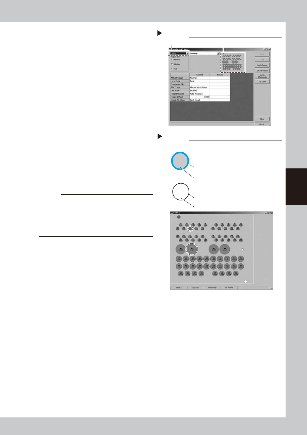
Open the "ANC Auto" screen.
1. Select a desired table from the pull-down
menu at the upper left of screen.
2. Click ANC figure on the right of screen.
54403-N9-00
6
Check the ANC sensor operation.
1. Check that the nozzle storage status
shown on the screen is the same as the
actual nozzle storage status referring to
the nozzle storage position/sensor status
in the figure.
2. Detach the nozzle manually and check
that no nozzle is displayed at the relevant
storage position.
54404-N9-00
7
Clean the ANC.
1. If the nozzle detection status is different
from the actual nozzle presence status,
remove the nozzle and visually check the
inside.
2. If any dust or chip is found, see "4.2
Cleaning nozzle station" to clean.
c
CAUTION
If the nozzle detection status inside the ANC does not
become stable for a reason other than clear reason,
such as dust, etc., or if the nozzle cannot be detected,
contact YAMAHA sales representatives. The disassembly
and cleaning performed by the customer are not
covered by the warranty.
8
Close the ANC shutter.
Press the [Nozzle. Stn Shutter] button to close
the ANC shutter.
Opening ANC Auto screen
Step 5
Select Table A or Table B. Click ANC figure.
5-513
13
6-SP
42
Checking ANC sensor operation
Step 6
513 nozzle to be used for head 5
Storage position: No. 13
Colored frame (red/blue/yellow/green, etc.):
Nozzle is already registered.
Special nozzle to be used for head 6
Storage position: No. 42
Black frame: Nozzle is not registered.
Gray out: Nozzle is present currently.
White: Nozzle is not present currently.
Example of nozzle storage position/sensor status
4-12
4
Maintenance of options
4.2 Cleaning nozzle station
The nozzle station is accumulated with dirt due to long-term use, although this may vary depending on the
machine operating environment. The spline (nozzle) shafts or filters get dirty through the nozzle if dirt remains
on the nozzle station. Therefore, it is recommended to clean nozzle station at the time when cleaning spline
shaft. This section describes how to clean nozzle station for MU head as an example.
n
NOTE
The nozzles can be easily detached from nozzle station with ANC nozzle attach/detach tool (hereafter "tool"). See
"1.2.4 ANC nozzle attaching/detaching tool" for details.
See "How to detach all nozzles for RS head" for nozzle station for RS head.
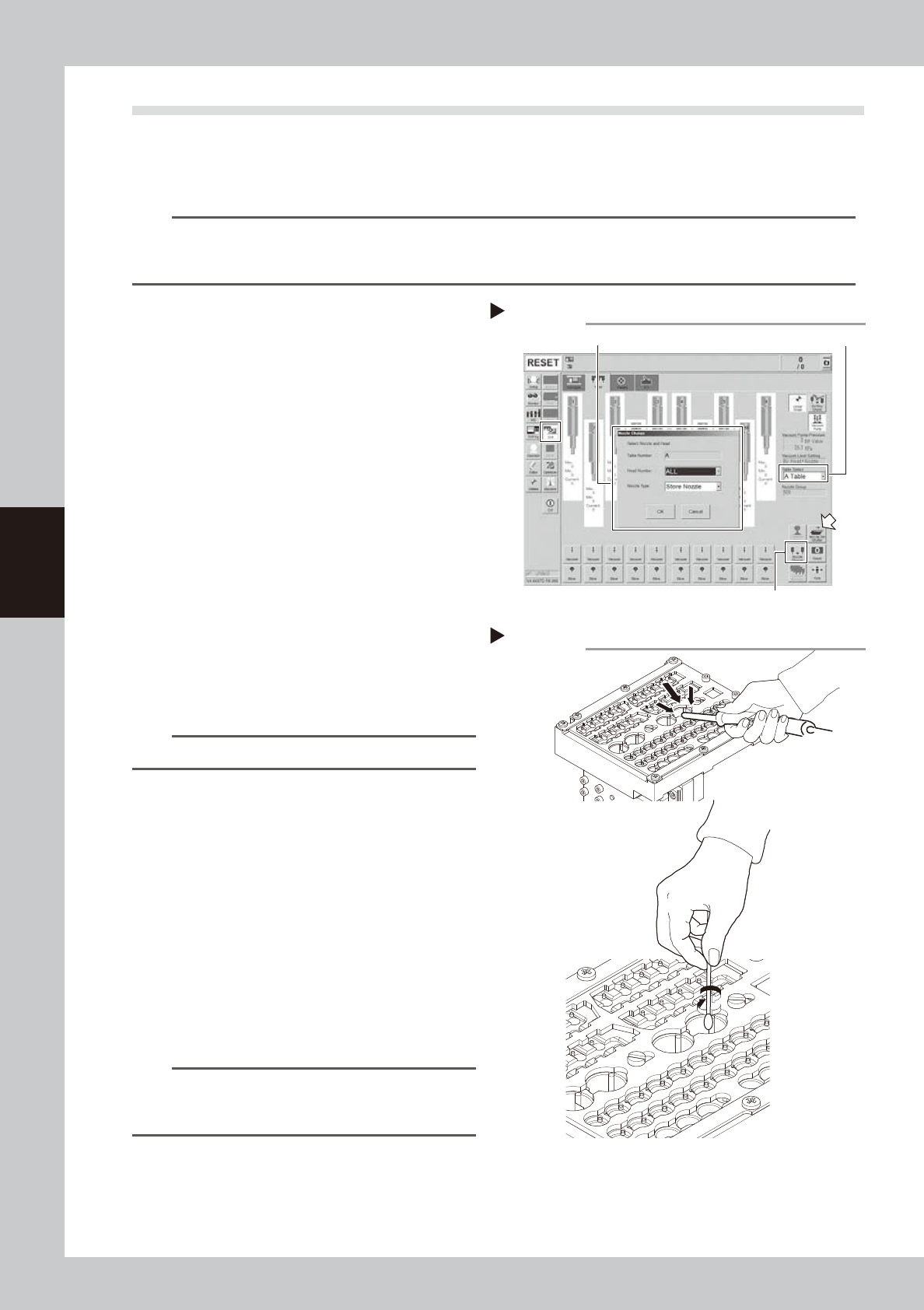
1
Store all nozzles to nozzle station.
1. Open the [Unit] - [Head] screen.
2. Select desired head unit from "Table
Select".
3. Press the [Nozzle Change] button.
4. Select "ALL" for "Head Number" and
select "Store Nozzle" for "Nozzle Type" on
the "Nozzle Change" screen.
5. Press the [OK] button to return all nozzles
to the nozzle station.
54405-N9-00
2
Close the nozzle station shutter.
Press the [Nozzle. Stn Shutter] button again
and close the nozzle station shutter.
e
3
Detach nozzles.
1. Press the emergency stop button and
then open the machine safety cover.
2. (With tool) See "How to detach all nozzles
for MU head" to detach nozzles.
TIP
Without tool, detach nozzles manually.
4
Check nozzle station.
Check visually that no dirt remains on nozzle
station.
5
Clean nozzle station.
1. Vacuum dirt on nozzle station with
vacuum assembly (option).
2. Apply IPA slightly to cotton swab to wipe
off the inside of nozzle station.
53416-N9-00
6
Return nozzles to original positions.
See "How to attach all nozzles for MU head"
to attach nozzles to nozzle station.
TIP
Without tool, return nozzles manually. See the nozzle
label adhered in machine or machine setting for nozzle
set positions.
Step 1,2
Storing nozzles
Head Number: “ALL” / Nozzle type: “Store Nozzle”
[Nozzle Change] button
Table Select
Cleaning nozzle station
Step 5

Chapter 5 Lubricating points
Contents
1. Lubricating preparations 5-1
1.1 Compatible grease 5-1
1.2 Grease gun 5-2
2. Lubricating points/schedule (Main machine) 5-3
2.1 X-axis 5-3
2.1.1 4-beam type 5-3
2.1.2 2-beam type 5-4
2.2 Y-axis 5-5
2.2.1 4-beam type 5-5
2.2.2 2-beam type 5-6
2.3 W-axis 5-7
2.4 PU-axis 5-8
2.5 Head unit 5-9
2.5.1 MU head unit 5-9
2.5.2 RS head unit 5-10
2.5.3 FL head unit 5-11
3. Lubricating points/schedule (Carriage) 5-12
3.1 Feeder exchange carriage 5-12
4. Lubricating points/schedule (cATS) 5-13
4.1 AZ-axis 5-13
4.2 AH-axis 5-14
4.3 Pickup station and others 5-15
4.4 Both sides of cATS 5-16