YSM40R_Mainte_E.pdf - 第160页
Chapter 4 Maintenance of options Contents 1. Ionizer 4-1 1.1 Cleaning ionizer discharge needle (Monthly) 4-2 1.2 Replacing ionizer discharge needle (2-year) 4-3 2. UPS (Uninterruptible Power Supply) 4-4 2.1 Replacing the…
3-89
3
Periodic maintenance items
9
Turn blow switch off.
Turn off the "Rod 1 (or 2)" valve and "Blow
switch" of cleaned head unit in reverse order
of Step 6.
0
Check vacuum level.
Check vacuum level without nozzles/filters.
See "How to check for clogged nozzles (on
the [Unit]-[Head] tab screen)" in Chapter 2.
• Reference value of vacuum level: 90 or less
If the vacuum level is out of the value,
perform Step 5 to 9 again for relevant nozzle
shaft.
q
Attach the filters.
1. See "2.6.1 Inspecting and replacing the
air filters" to attach new filters to all heads.
2. Remove square cloth after working.
w
Return spools to original position.
1. Close the machine cover and set
carriage.
2. Cancel the emergency stop.
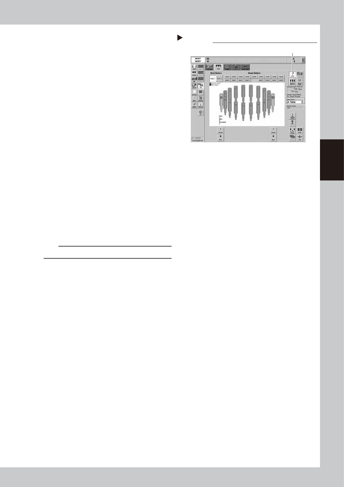
3. Open [Unit] - [Head] screen.
4. Select the table to perform the work.
5. Pressing [Recover Valve Pos] returns
spools to the reset positions.
54307-N9-00
TIP
The [Recover Valve Pos] is a vacuum position.
Recovering valve position
Step 12
[Recover Valve Pos] button

Chapter 4 Maintenance of options
Contents
1. Ionizer 4-1
1.1 Cleaning ionizer discharge needle (Monthly) 4-2
1.2 Replacing ionizer discharge needle (2-year) 4-3
2. UPS (Uninterruptible Power Supply) 4-4
2.1 Replacing the UPS battery (3 year) 4-4
3. Inspecting, cleaning and lubricating cATS 4-5
3.1 Daily inspection 4-6
3.1.1 Inspecting magazines and pallets 4-6
3.2 Monthly inspection 4-7
3.2.1 AZ-axis 4-7
3.2.2 Both sides of cATS 4-7
3.3 6-month inspection 4-8
3.3.1 AH-axis 4-8
3.3.2 Magazine shaft 4-8
3.3.3 Pickup station (pallet clamp) 4-9
3.3.4 Pickup station (vertical guide) 4-9
4. Nozzle station 4-10
4.1 Checking nozzle station sensor (1-year) 4-10
4.2 Cleaning nozzle station 4-12
4-1
4
Maintenance of options
1. Ionizer
As the ionizer is used for a long time, the discharge needle (electrode) is worn out and deteriorates.
Additionally, the periodic cleaning work is needed to maintain the static elimination effect and ion balance.
c
CAUTION
A voltage is applied to the discharge needle tip of the ionizer. Be careful not to touch the tip directly by hand when
performing the maintenance work inside the machine.
n
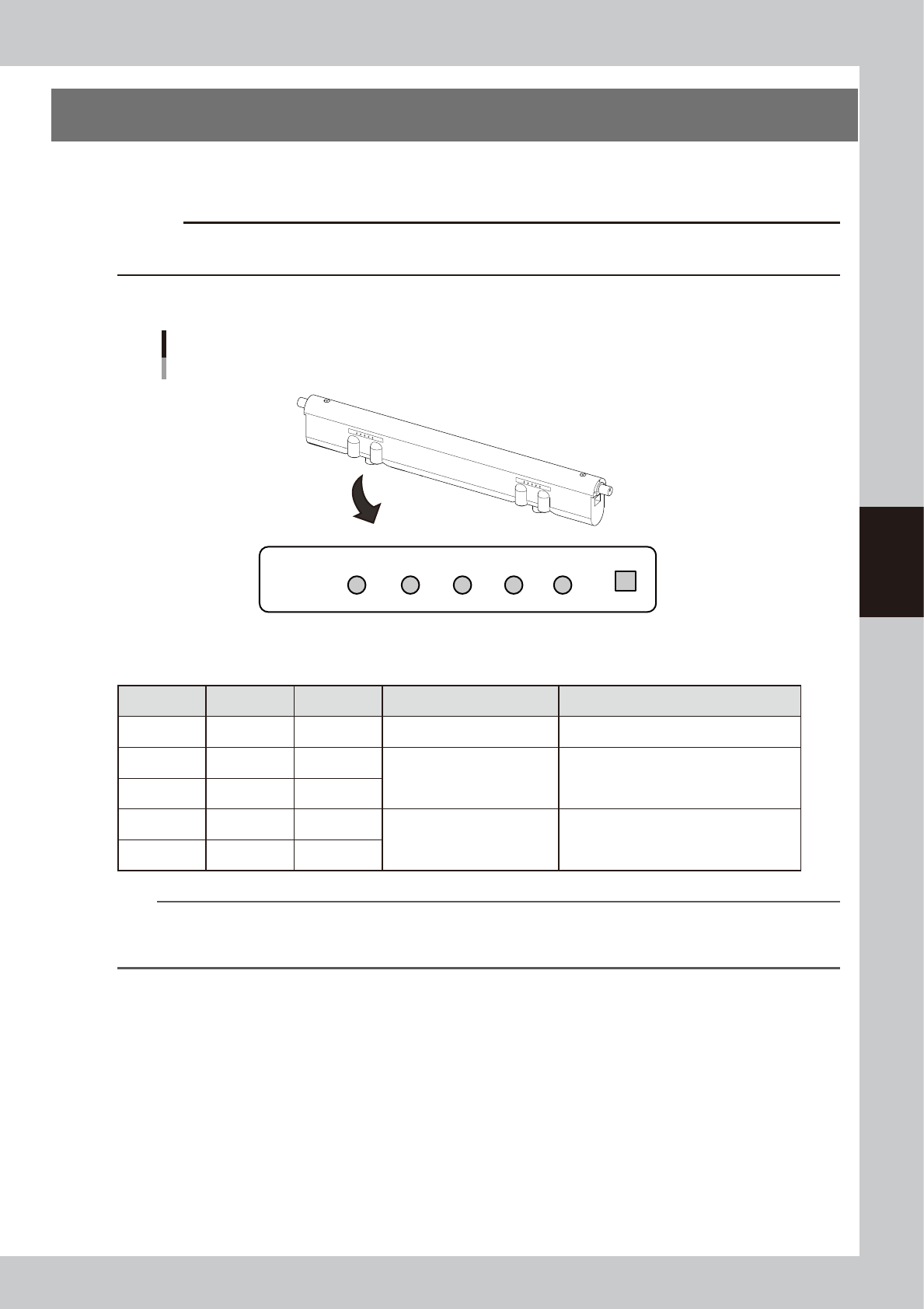
LED display on ionizer main unit
+ -
Trinc
ERR PREC GOOD PREC ERR
Ionizer
Contents of LED display
LED display is provided at two locations of each ionizer.
53400-N9-00
n
Ionizer indication
LED Color Light Status Remarks
GOOD
Blue Lighting Normal operation
+PREC
Green Lighting
Large ion balance correction
amount
The contamination of the discharge needle
advances. The discharge needle needs to
be cleaned.
− PREC
Green Lighting
+ERR
Red Flashing
Ion balance error
The discharge needle may be contaminated
or deteriorate significantly. The relevant
error is also given on the machine side.
− ERR
Red Flashing
n
NOTE
The performance and capability of the ionizer to remove static electricity depends on the operating environment or
the materials and shape of the items that the static electricity is removed. YAMAHA does not guarantee such
performance or capability.