YSM40R_Mainte_E.pdf - 第84页
3-14 3 Periodic maintenance items e 1. Press the emergency stop button and then open the machine safety cover . 2. Set the tool as the "A/D-T able Front" on tool is not upside down. Insert the tool into nozzle …
3-13
3
Periodic maintenance items
Attach nozzles at the nozzle station in the reverse order of detaching.
This section describes the procedure with "A/D Table Front" as an example.
1
Check the nozzle setting position.
Check that other nozzles are not set to the
nozzle storage positions and the setting
position is correct.
n
NOTE
See the nozzle placement position label attached in
the machine or the machine setting for the nozzle
setting position.
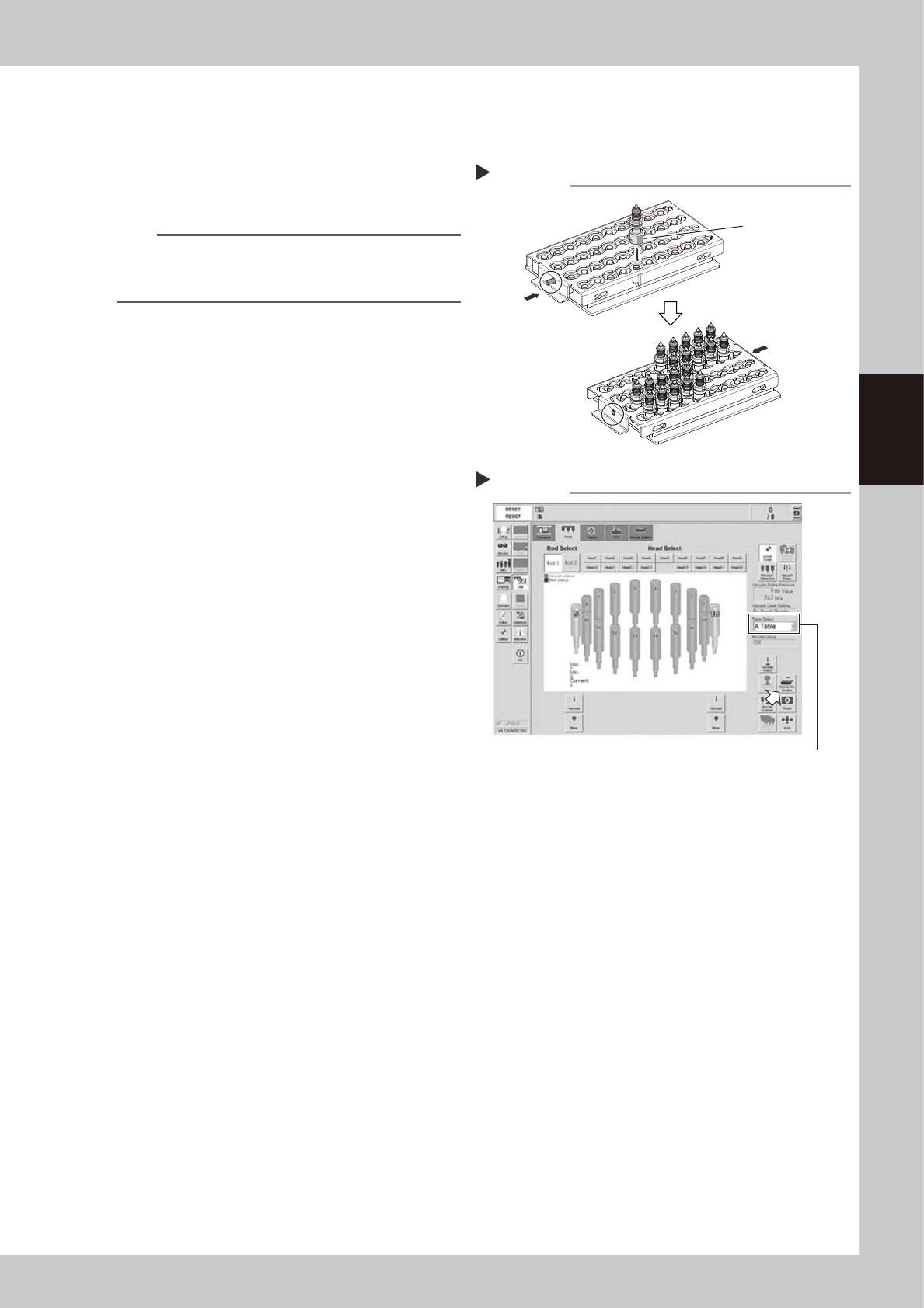
2
Set nozzles in the tool.
1. Push the "RELEASE" side to release all
nozzles.
2. Insert a nozzle facing the nozzle flat
surface to pin side.
3. After inserting all nozzles, push the
"CLAMP" side to clamp all nozzles.
543E0-N9-00
3
Open the nozzle station shutter.
1. Open [Unit] - [Head] screen
2. Select head unit from "Table Select".
3. Press [Nozzle. Stn Shutter] button to open
the nozzle station shutter.
54303-N9-00
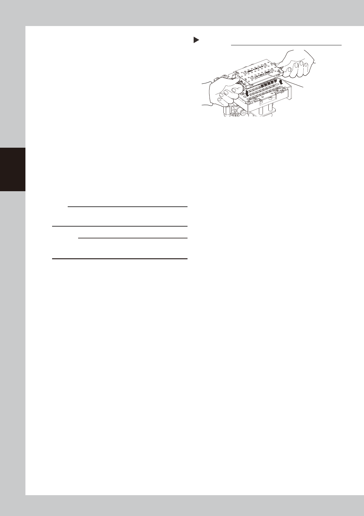
4
Set the tool on the nozzle station.
Step3
Nozzle station - Opening the shutter
Table Select
Setting nozzles
Step 2
CLAMP
RELEASE
Nozzle flat surface
3-14
3
Periodic maintenance items
e
1. Press the emergency stop button and
then open the machine safety cover.
2. Set the tool as the "A/D-Table Front" on
tool is not upside down. Insert the tool
into nozzle station aligning ANC mark
and tool mark.
3. Check that the tool is set to nozzles
securely.
533F0-N9-00
5
Close the nozzle station shutter.
Press the [Nozzle. Stn Shutter] button again
and close the nozzle station shutter.
6
Detach nozzles from tool.
1. Push the "RELEASE" side to release all
nozzles.
2. Raise the tool up vertically and slowly
and detach the nozzles from the tool.
3. Close the machine safety cover and
cancel the emergency stop.
n
NOTE
Raise the tool up vertically and slowly to avoid the
nozzle tip from hitting the shutter, etc.
c
CAUTION
If raising the tool up fast and forcibly, nozzles or the
nozzle station may be damaged.
Attaching all nozzles
Step 4
“A/D-Table FRONT”
3-15
3
Periodic maintenance items
1.3 Vision system
1.3.1 Cleaning the multi-vision camera lighting's protective cover
Adhered dust, etc., on the multi-vision camera lighting's protective cover can cause component recognition
errors. To prevent this, inspect and clean the cover in a periodic manner.
e
1
Press the emergency stop button.
Press the emergency stop button and then
open the machine safety cover.
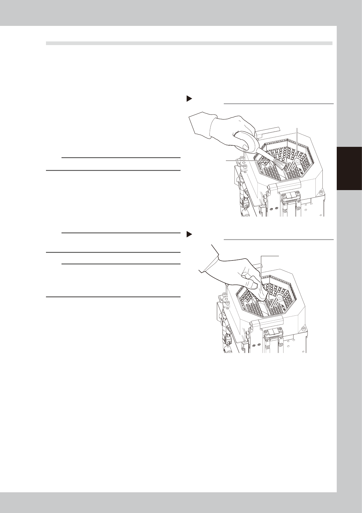
2
Use blower brush to remove any
dust from the lighting's protective
cover.
53310-N9-00
TIP
A lens blower brush is available as an option.
3
Wipe the lighting's protective cover
with a cloth.
Wipe the lighting's protective cover with a
cloth which has been dampened with a
small amount of lens cleaner.
53311-N9-00
n
NOTE
Use a lint-free cleaning cloth or paper wiper.
A lens cleaner is optional item.
n
NOTE
If dust or debris still remains even after cleaning as
described above, clean the backside of the protective
cover and the light-emitting surface referring to "4.1.2
Multi-vision camera" in this chapter.
Wiping protective cover
Step 3
Lint-free cleaning cloth
Step 2
Blowing off dust with blower brush
Protective cover (glass)
Bower brush